832 Wirecube
832 : Wirecube
- Author: Leo Moser
- Description: A demo for the Tiny Tapeout demoscene competition - see for yourself!
- GitHub repository
- Open in 3D viewer
- Open in Tiny Tapeout Explorer
- Clock: 50350000 Hz
- Feedback: ✅ 1
How it works
The central point of this demo revolves around an optimized implementation of a technique known as the edge function. The edge function is used to determine if a point lies to the left or right of a line. Typically, a pixel is tested against all three sides of a triangle to decide whether it lies inside the triangle and should be coloured accordingly.
In this demo, however, I'm using the magnitude of the edge function to decide whether a pixel should be colored as part of a line: If the magnitude is smaller than a certain threshold, then the pixel is considered to be part of the line. This can be used to render wireframe geometry. By changing the threshold, the thickness of the wires can be adjusted.
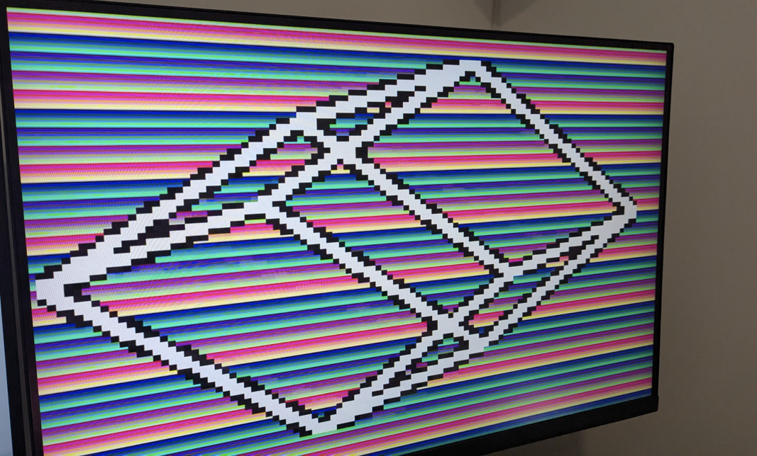
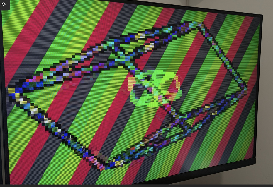
The demo renders a three-dimensional rotating wireframe cube. The points of the cube are not generated on the fly, instead, they are stored in a ROM. By ordering the points so that the first point is always to the left and below the second point the implementation of the edge function can be optimized further. The coordinates are scaled by half to create the points for a second, smaller, rotating cube. Alternating between these two cubes every other frame creates the illusion that they exist at the same time.
How to test
Connect a Tiny VGA to the output Pmod port, set the clock frequency to two times 25.175 MHz = 50.350 MHz, make sure ui_in is set to 0x00 and enjoy the show!
 |
 |
 |
 |
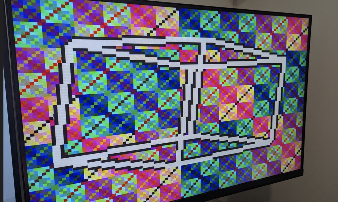
If you want to mix things up, try these settings:
ui_in[2:0]is used to change the background fill colorui_in[5:3]is used to change the cube line fill colorui_in[7:6]is used to change the animation speed
External hardware
IO
| # | Input | Output | Bidirectional |
|---|---|---|---|
| 0 | toggle background bit 0 | R1 | |
| 1 | toggle background bit 1 | G1 | |
| 2 | toggle background bit 2 | B1 | |
| 3 | toggle cube bit 0 | VS | |
| 4 | toggle cube bit 1 | R0 | |
| 5 | toggle cube bit 2 | G0 | |
| 6 | toggle speed bit 0 | B0 | |
| 7 | toggle speed bit 1 | HS |
User feedback
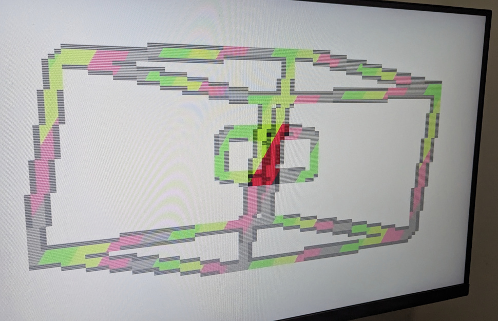
- urish: Rotating wireframe cube (or two) with cool effects. Sometimes it even stops rotating and turns into a sole rectangle! Link for more details