GPIO pins
There are total of 26 I/O pins available for your design:
| Name | Count | Direction | Description |
|---|---|---|---|
clk |
1 | Input | Clock input |
rst_n |
1 | Input | Active low reset |
ui_in[7:0] |
8 | Input | General purpose input |
uo_out[7:0] |
8 | Output | General purpose output |
uio[7:0] |
8 | Bidir | General purpose I/O |
Internally, both the clk and rst_n pins are handled like any other input pins. However, they have special meaning to the Tiny Tapeout devkit. For more information on the clk pin and input synchronization, see the Clock section.
Limitations
The chip uses the sky130_ef_io_gpiov2_pad macro for the I/O pads. The documentation lists the following limitations:
| Parameter | Limitation |
|---|---|
| Maximum output frequency | 33 MHz |
| Maximum input frequency | 66 MHz |
| Drive strength (source/sink) | 4 mA |
| IO supply voltage * | 1.71V - 5.5V |
* The demo board provides 3.3V IO supply voltage. The input pins are not 5V tolerant.
f_max versus IO Maximum Frequency
The f_max of the project is dictated by what the project is - the logic itself. Once the project is synthesized, the
static timing analyzer (STA) will look at your logic and spit out a number which is the maximum frequency that you can
safely clock your project at. This number depends on the process/voltage/temperature (PVT) corners, so you’ll get
several numbers. For Tiny Tapeout, the typical (tt) corner is generally reached, but you can also check the slow (ss)
corner to check the worst case scenario.
The maximum IO frequency is dictated by the IO pads themselves and the infrastructure that we put in the path of the signal.
The maximum input frequency is the maximum frequency you can input a signal into the pad and still expect to get that signal to your tile with minimal distortion. For SKY130 the IO pads themselves are rated to 66 MHz - and we expect our infrastructure to work fine there too. This doesn’t mean that it stops working if you go above 66 MHz - that is just the official rating given by SkyWater. Above 66 MHz, the signal can start to distort, mostly because falling edges propagate faster than rising edges (due to NMOS transistors being better than PMOS ones). People have gotten a signal in the 100 MHz range and it worked, but it shouldn’t be relied upon and your mileage will vary.
The maximum output frequency is the maximum frequency you can toggle an output pad at. Again, limited by the provided output pads, our infrastructure and the actual loading of the pad. For SKY130 the official rating is 33 MHz, however the documentation is unclear whether that means the toggle rate of the pad or if a 33 MHz square wave can be output. In practice, you can output a 33 MHz square wave and it still looks acceptable - albeit with some asymmetry - if the load isn’t large. People have driven the clock line of the QSPI Pmod at 32 MHz successfully.
In the context of low-voltage differential signalling (LVDS), an LVDS input could be driven at ~65-70 Mbps using a fake differential. The slow slew rate of the pads means that if you have several symbols (0, 1) of the same value, the output will go to the full 0V/3.3V. When the symbol changes, the outputs might not have enough time to swing to the correct value in the given time period for a single symbol.
Electrical Characteristics
Note: the following measurements were taken on a single die at ~22 °C and may not be representative of future batches. They are only provided for reference.

Sink IV Curve
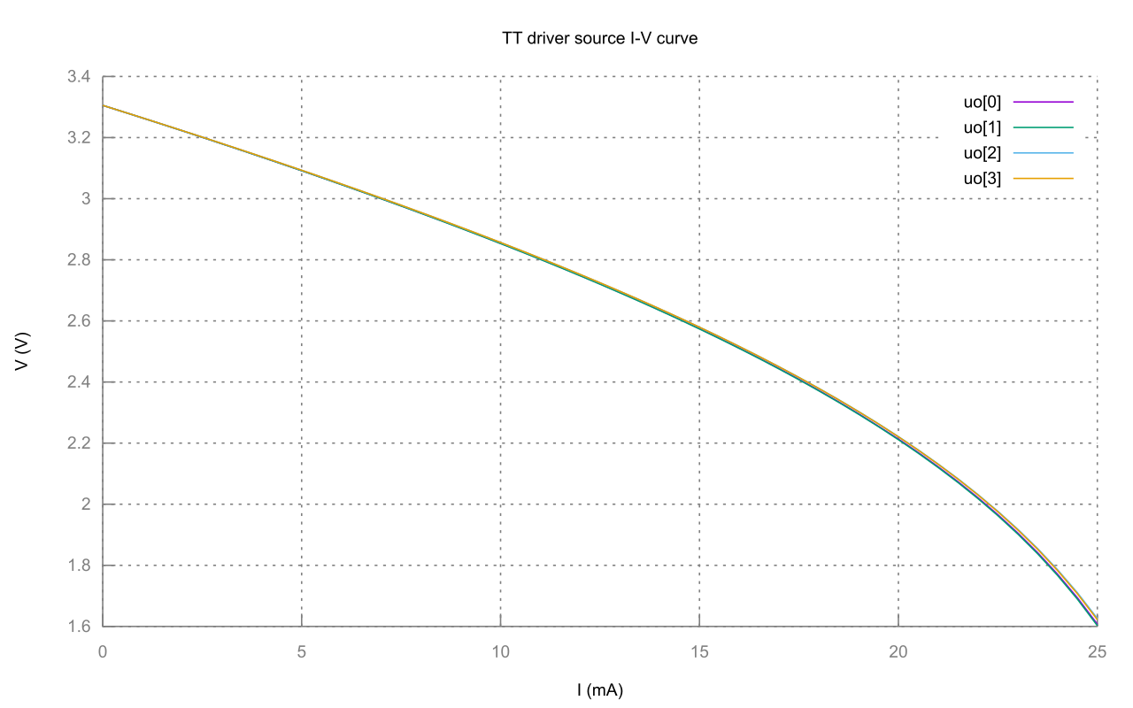
Source IV Curve
Multiplexer measurements
Note: the following measurements were taken on a single die at ~22 °C and may not be representative of future batches. They are only provided for reference.
After Tiny Tapeout 3.5 silicon was received and tested the worst round trip latency was measured to be 20 ns as shown in the following scope screen captures.
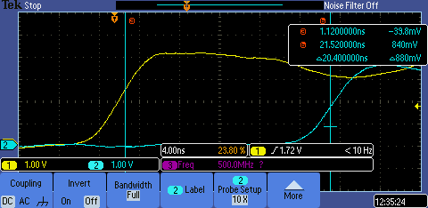
Rising edge latency
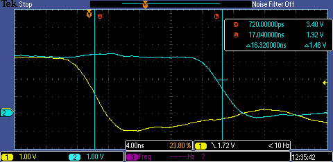
Falling edge latency
Delay variance between different IO pins has been measured at less than 2ns.