FPGA ASIC simulator breakout
With this FPGA board you don’t have to wait for an ASIC to test your digital design.
Here we’ll:
Overview
The FPGA breakout has a Lattice UP5K FPGA on a PCB with headers and a pinout compatible with the Tiny Tapeout demoboard, which includes all the digital I/O as well as the project reset and clock (both routed to global buffer input pins on the FPGA).
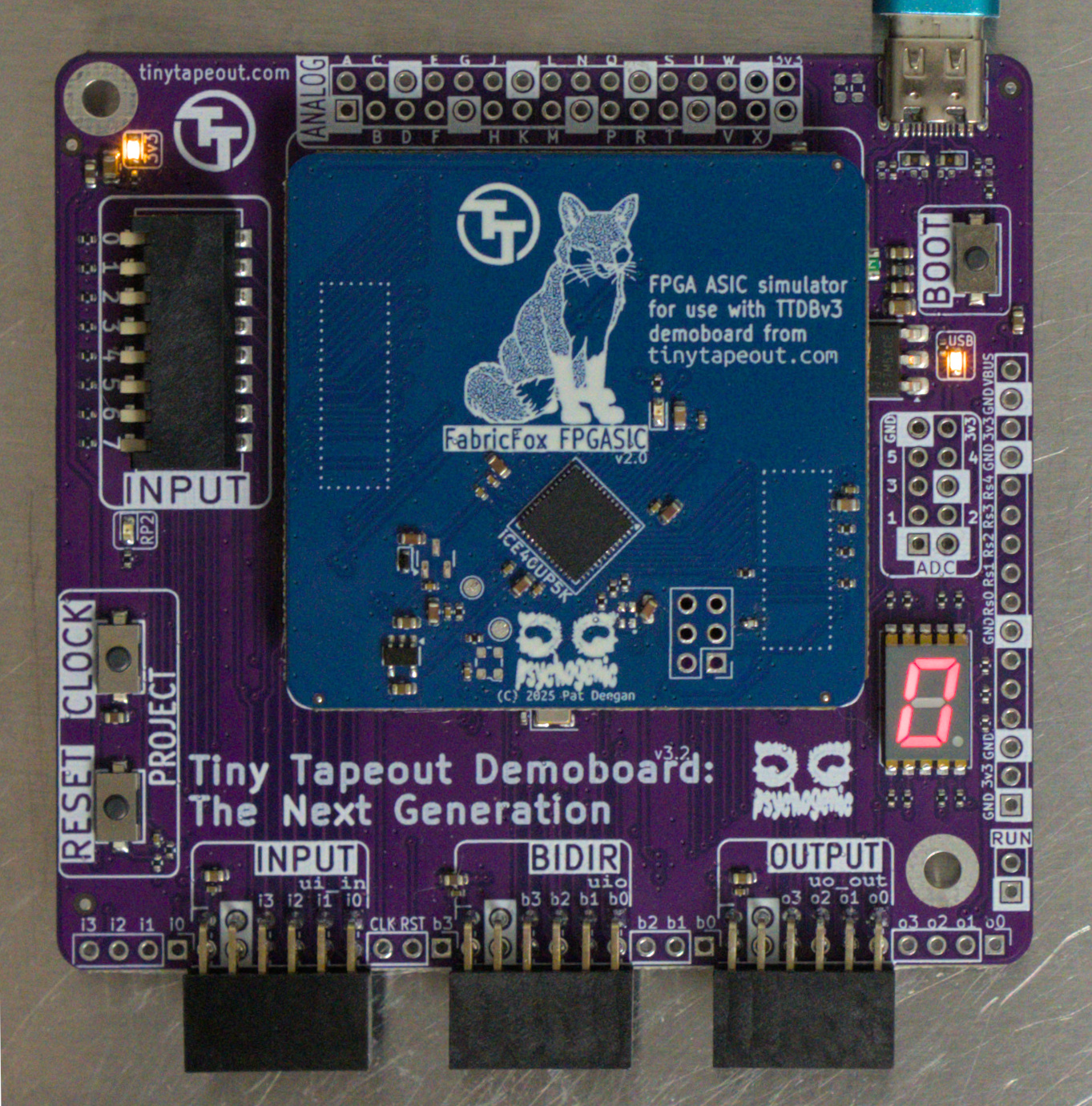
FPGA breakout on demoboard
The board has a LED to indicate the unprogrammed state.
The FPGA awaits configuration on power-up/reset and the demoboard can handle this through FPGA reset and SPI lines. Just as you would with a TT ASIC, on the demoboard REPL provided with the microPython SDK, you can use the shuttle to enable any of the bitstreams present, e.g.
>>> tt.shuttle.tt_um_factory_test.enable()
This will reset the FPGA, and feed the contents of the bitstreams/tt_um_factory_test.bin file to configure the FPGA. All the standard SDK features work as well, so if there’s a relevant section in the config.ini file specifying, say, a clock frequency then the project will be auto-clocked on loading.
Harden a Design
It is easy to harden Verilog projects targetting the FPGA breakout.
Requirements and Setup
-
OSS-CAD-Suite to provide Yosys, and the rest of the open source FPGA toolchain;
-
The PCF file that indicates the pin mappings and lets the PnR complete the process; and
-
Resulting bitstream binary files must be uploaded to the right place (under
/bitstreams) on the demoboard.
To handle the specifics related to our boards and SDK, the Tiny Tapeout Tools include utilities that make life a lot easier.
Four steps for setup:
-
Follow the directions for OSS CAD Suite Installation on your platform;
-
Enable the OSS CAD Suite environment. E.g. under linux
  user@computron:~$ source /path/to/oss-cad-suite/environment
  ⦗OSS CAD Suite⦘ user@computron:~$
- Get the TT support tools
⦗OSS CAD Suite⦘ user@computron:~$ git clone https://github.com/TinyTapeout/tt-support-tools.git tt
The top level directory may have any name and be placed anywhere on your system, the important thing is that we be able to call the scripts within. Here we’ll assume the tools are installed under ~/tt/.
- Install the TT support tools requirements
 ⦗OSS CAD Suite⦘ user@computron:~$ cd tt
 ⦗OSS CAD Suite⦘ user@computron:~/tt$ pip install -r requirements.txt
You can test your installation by running one of the scripts now. That should look like, e.g.:
  ⦗OSS CAD Suite⦘ user@computron:~$ ~/tt/tt_fpga.py --help
  TT FPGA tool

  positional arguments:
    {harden,configure}        Available commands
      harden                  Run hardening process
      configure               Upload bitstream and manage configuration

  options:
    -h, --help                show this help message and exit
    --project-dir PROJECT_DIR location of the project
    --debug                   debug logging
Harden a Tiny Tapeout Design
If you have a design based on a Tiny Tapeout Verilog Template, then you have a configured info.yaml file which makes the process of targetting the FPGA boards very easy. Follow this process:
-
Be sure you’ve installed and setup the requirements above
-
Enable the OSS CAD Suite environment
  user@computron:~$ source /path/to/oss-cad-suite/environment
  ⦗OSS CAD Suite⦘ user@computron:~$
- Be inside your project’s top level directory, e.g.
  ⦗OSS CAD Suite⦘ user@computron:~$ git clone https://github.com/TinyTapeout/ttsky25b-factory-test.git ftest
  ⦗OSS CAD Suite⦘ user@computron:~$ cd ftest
  ⦗OSS CAD Suite⦘ user@computron:~/ftest$ ls
  docs  info.yaml  LICENSE  README.md  src  test
- Harden the design by running
tt_fpga.pywith the harden argument
 (OSS CAD Suite⦘ user@computron:~/ftest$ ~/tt/tt_fpga.py harden

 2026-01-17 10:03:09,518 - tt_fpga    - INFO     - Creating FPGA bitstream for [000 : unknown]
 /----------------------------------------------------------------------------\
 |  yosys -- Yosys Open SYnthesis Suite                                       |
 |  Copyright (C) 2012 - 2025  Claire Xenia Wolf <[email protected]>         |
 |  Distributed under an ISC-like license, type "license" to see terms        |
 \----------------------------------------------------------------------------/


 [... snip ... ]


 Info: [ 37080,  37234) |
 Info: [ 37234,  37388) |**
 Info: [ 37388,  37542) |
 Info: [ 37542,  37696) |**

 Info: Program finished normally.
 2026-01-17 10:03:10,190 - tt_fpga - INFO - Bitstream created successfully: ~/ftest/build/tt_um_factory_test.bin
And you are done. The bitstream will be present within the build/ sub-directory, named according to the top level module specified in the info.yaml file.
Harden any Verilog design
The above is really the simplest way to do this, but you don’t actually need to have the info.yaml or to have used the Tiny Tapeout template to leverage the tt-support-tool.
If you simply try to run ~/tt/tt_fpga.py harden as above, you will get an error
 ⦗OSS CAD Suite⦘ user@computron:~/ftest$ ~/tt/tt_fpga.py harden
 2026-01-17 10:10:18,520 - tt_fpga    - INFO     - Creating FPGA bitstream for None
 No project yaml, must specify source_dir
However, the tt_fpga.py script provides a number of options to allow you to specify what the script normally gets through the info.yaml. The harden --help argument lists available options and flags
 (OSS CAD Suite⦘ user@computron:~/ftest$ ~/tt/tt_fpga.py harden --help
 usage: tt_fpga.py harden [-h] [--name FILE] [--breakout-target {classic,fabricfox}] [--source_dir DIR] [--source FILE] [--top_module TOP]

 options:
  -h, --help            show this help message and exit
  --name FILE           Output file and project name (default: top_module name)
  --breakout-target {classic,fabricfox}
                        Select target breakout: classic (TT04), fabricfox (TT ETR db) default: fabricfox
  --source_dir DIR      Directory containing source verilog files (default from info.yaml)
  --source FILE         Source file(s) to harden (specify multiple times for multiple source files, default from info.yaml)
  --top_module TOP      Name of the top module (default from info.yaml)
The only required arguments are --top_module --source_dir and as many --source arguments as you have .v files you wish to include.
Steps:
-
Be sure you’ve installed and setup the requirements above
-
Enable the OSS CAD Suite environment
  user@computron:~$ source /path/to/oss-cad-suite/environment
  ⦗OSS CAD Suite⦘ user@computron:~$
- move to within your project top level directory
user@computron:~$ cd /path/to/project
- Harden the design by running
tt_fpga.pywith the harden argument along with the required information, to get the bitstream binary file generated.
 (OSS CAD Suite) user@computron:/path/to/project$ ~/tt/tt_fpga.py harden --top_module tt_um_factory_test \
                                               --source_dir src  --source tt_um_factory_test.v


 [ ... snip ... ]

 Info: Program finished normally.
 2026-01-17 10:14:51,166 - tt_fpga - INFO - Bitstream created successfully:
 /path/to/project/build/tt_um_factory_test.bin
Get the Design Running
You generated a valid bitstream, using the process above, but now it’s just sitting on your computer. This is how to get it running on the FPGA.
If you are using Linux, you may need to add yourself to a group to use serial - typically either dialout or uucp.
Check which group the device file representing the devkit is using by running ls -l /dev/ttyACMX (where X is a number,
automatically assigned by your OS - usually 0 if it is the only serial device plugged in).
Run sudo adduser $USER <group> in the terminal - you may need to restart your PC for the changes to apply.
The SDK will actually treat any *.bin file in /bitstreams on the demoboard filesystem as an available project. Meaning that when you are on the uPython REPL, you can do
>>> tt.shuttle.my_project.enable()
To load it, assuming there’s a /bitstreams/my_project.bin file in there.
To make uploading and configuring the bitstreams easier, the tt_fpga.py script also has a configure command.
 $ ~/tt/tt_fpga.py configure --help
 usage: tt_fpga.py configure [-h] [--port COMPORT] [--set-default] [--upload] [--clockrate RATE] [--name FILE]

 options:
  -h, --help        show this help message and exit
  --port COMPORT    Port for uploads (default: /dev/ttyACM0)
  --set-default     set this project as the default on startup
  --upload          upload the bitstream.bin from build/
  --clockrate RATE  Clock rate in Hz
  --name FILE       Output file and project name (default: top_module name)
Bitstream Installation
Though you can use any means to get the bitstream installed, the --upload flag makes this easy.
For projects based on the Tiny Tapeout template, this is as simple as
$ ~/tt/tt_fpga.py configure --port /dev/ttyACM0 --upload
The --port is where your demoboard is found, so /dev/ttyACMX under Linux, COMsomething with windows.
If you are running this via the Windows Subsystem for Linux (WSL) and the command above fails, you may need to pass the
device manually or to use a different port.
WSL 1 users: COMX is mapped to /dev/ttySX (where X is a number). See the docs for more info.
WSL 2 users: Please follow Microsoft’s own guide on connecting USB devices to WSL 2.
It makes use of the usbipd-win project.
If you hardened this bitstream without an info.yaml you can specify the name of the project that was previously generated to help the script find which .bin you’re uploading
$ ~/tt/tt_fpga.py configure --port /dev/ttyACM0 --upload --name my_project
Project Configuration
You can configure how projects are loaded and which project is loaded on power-up through the config.ini file, but the configure command can also make this simpler for you.
To set your project as the default to load on power-up, use the --set-default flag.
To specify a clock rate to auto-clock the project at on load, use the --clockrate option.
You may combine all of these, including upload, into a single command
 $ ~/tt/tt_fpga.py configure --port /dev/ttyACM0 --upload \
                           --name my_project \
                           --set-default \
                           --clockrate 2000000