Laying Out Standard Cells with Magic VLSI
Magic VLSI is a layout tool that allows you to draw your own features, but to also use cells from existing PDKs to create your design. This guide will take you through placing cells from the SkyWater 130nm PDK and how to wire them together.
Preparing Magic VLSI
Magic is available as a downloadable AppImage for Linux. It can also be compiled from source - see github.com/rtimothyEdwards/magic for more information. For Windows users, follow this guide: opencircuitdesign.com/cygwin/magic.html.
Installing a PDK
To have access to the standard cells that we want to place, we must first download the PDK which contains these cells.
As stated in the introduction, we are looking to use the SkyWater 130nm PDK - this is also known as sky130.
We will use ciel - a dedicated version manager and installer for open source PDKs. ciel is available via Python’s
pip. You must have Python 3.8+ installed on your machine. Detailed installation instructions are available at
github.com/fossi-foundation/ciel.
Downloading ciel
Install ciel using pip via the terminal:
python3 -m pip install --user --upgrade --no-cache-dir ciel
Check if it has been installed properly with:
ciel --version
Enabling the sky130 PDK
ciel is capable of fetching and enabling different versions of open source PDKs. These versions are identified by
a commit hash - exactly the same hash that you may be familiar if you have used git before.
We can see which PDKs are currently available by running ciel ls-remote --pdk-family sky130.
Pre-built sky130 PDK versions
├── 9233c19260cd813c3fa67dd4594fe4cc67016832 (2026.06.05)
├── bc317490f716a2ed2e6f99eb190756fb9713d732 (2026.05.30)
├── 42fa7a6d046df816feb335f529277eb66ddcf96b (2026.05.28)
├── f3b5e46babb6b417f9a1a1b5c413f7dda6f68a51 (2026.05.27)
├── 61a056e180dac7dcc6d4eb7529e2231f95105746 (2026.05.25)
├── 1c8019c4421c99348a0ec78f4e969eed6fb5c647 (2026.05.24)
├── 74c0e6b118a67d94c24172143d3bd597473fa63d (2026.05.21)
[...]
We will install the current latest version of the sky130 PDK - this is commit hash 9233c19260cd813c3fa67dd4594fe4cc67016832.
To do so, we will run ciel enable --pdk-family sky130 9233c19260cd813c3fa67dd4594fe4cc67016832. This may take a few
moments to download, depending on your internet connection.
Version 9233c19260cd813c3fa67dd4594fe4cc67016832 not found locally, attempting to download…
Downloading common.tar.zst… ━━━━━━━━━━━━━━━━━━━━━━━━━━━━━━━━━━━━━━━━ 100% 0:00:00
Downloading sky130_fd_io.tar.zst… ━━━━━━━━━━━━━━━━━━━━━━━━━━━━━━━━━━━━━━━━ 100% 0:00:00
Downloading sky130_fd_pr.tar.zst… ━━━━━━━━━━━━━━━━━━━━━━━━━━━━━━━━━━━━━━━━ 100% 0:00:00
Downloading sky130_fd_sc_hd.tar.zst… ━━━━━━━━━━━━━━━━━━━━━━━━━━━━━━━━━━━━━━━━ 100% 0:00:00
Downloading sky130_fd_sc_hvl.tar.zst… ━━━━━━━━━━━━━━━━━━━━━━━━━━━━━━━━━━━━━━━━ 100% 0:00:00
Downloading sky130_ml_xx_hd.tar.zst… ━━━━━━━━━━━━━━━━━━━━━━━━━━━━━━━━━━━━━━━━ 100% 0:00:00
Downloading sky130_sram_macros.tar.zst… ━━━━━━━━━━━━━━━━━━━━━━━━━━━━━━━━━━━━━━━━ 100% 0:00:00
Version 9233c19260cd813c3fa67dd4594fe4cc67016832 enabled for the sky130 PDK.
By default ciel will download the PDK to ~/.ciel. This can be modified by setting $PDK_ROOT.
Launching Magic
You will need to use the correct arguments when launching magic in order to load any installed PDKs. These arguments do
vary slightly between the different PDKs, so we will only cover the sky130 one here.
Run the following: magic -rcfile ~/.ciel/sky130A/libs.tech/magic/sky130A.magicrc to launch magic.
You may also set and use $PDK and $PDK_ROOT, in which case, your command may look something like: magic -rcfile ${PDK_ROOT}/${PDK}/libs.tech/magic/${PDK}.magicrc.
This may be useful if you have been following the local hardening guide and have already set those
variables.
A how-to guide for magic is available: opencircuitdesign.com/magic/howto.html.
Setting the Grid
First, set the grid to 0.46um by 0.36um and enable grid snapping by running the following commands:
grid 0.46um 0.34um
snap user
This grid matches the “hd” (high density) cells - for other cell types, you can find the grid sizes in the second table
in the SkyWater PDK docs. The
relevant rows are X-GRID and Y-GRID.
Instantiating the Cells
You can browse the standard cell catalog in the “libmgr” panel. Open the “Options” menu and select “Library Manager”.
You’ll see a list of all the libraries and their cells inside. We are using the high density library, so make sure you’re
picking cells from the sky130_fd_sc_hd library. Select a cell and click “Place” to add it to your design, or “Pick”
to manually position it.
You can move an already placed cell by first hovering over it and pressing I, and then moving your cursor elsewhere and pressing M. It will move the bottom-left of the cell to where your cursor is.
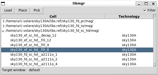
Library Manager window
If you know the name of the cell you’d like to place, you can also use the getcell command to place it, e.g.: getcell sky130_fd_sc_hd__inv_1
The meaning of sky130_fd_sc_hd is as follows: sky130 = node name, fd = foundry, sc = standard cells, hd = high density.
Placing the Cells
The standard cells are placed in rows. You must include a tap cell within 15um of every transistor (e.g. sky130_fd_sc_hd__tapvpwrvgnd_1),
and the cells should slightly overlap each other. If you are missing tap cells, you’ll get DRC errors.
Adhering to the grid settings defined above ensures the overlapping parts of the cells match - otherwise, you’ll get DRC errors.
Here’s an example of three cells placed, showing how they overlap. The other white rectangle is a sky130_fd_sc_hd__tap_1,
which partially overlaps the two surrounding cells.
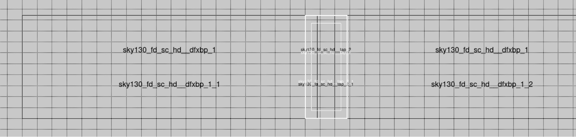
2 DFFs with a tap cell in the middle, grid overlay
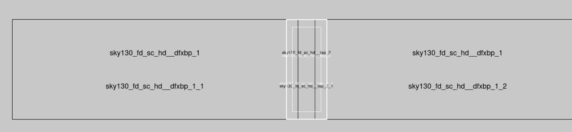
2 DFFs with a tap cell in the middle, no grid overlay
In this example, we’re using the dfxbp cell, which is a delay flip-flop with complementary outputs.
To show the contents of a cell, move the mouse over it, press I and then press X (for “expand”). To hide the contents of a cell, press Shift + X.
Placing Multiple Rows
You can stack multiple rows on top of one another by mirroring the cells vertically on every other row. To mirror a cell vertically, select the instance (by moving the mouse over it and pressing I), then press Shift + F.
The cells should overlap each other, as shown in the figure below.
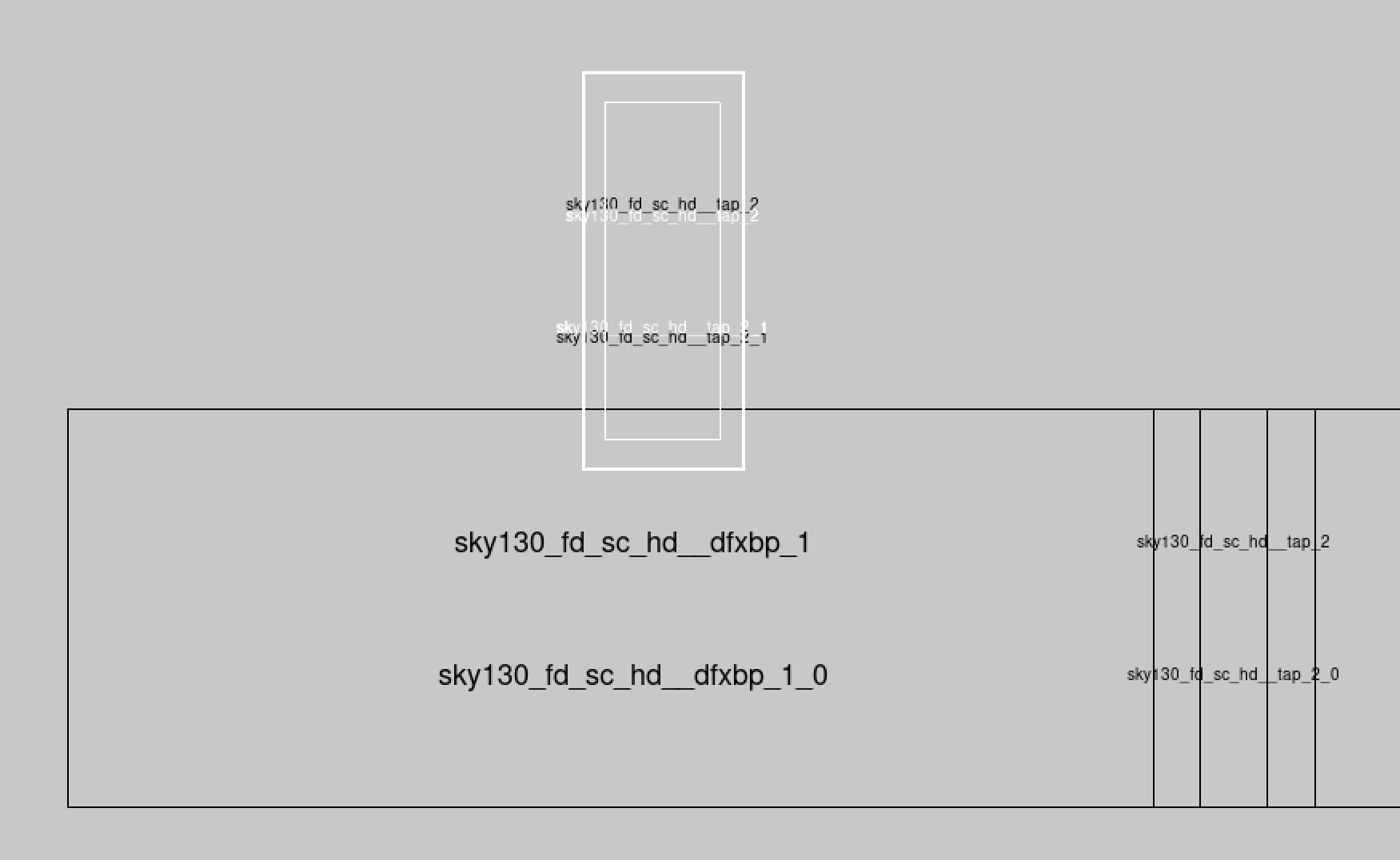
A tap cell overlapping a DFF cell
If you are getting DRC errors, you either forgot to flip the cells, or are not snapping the cells to the grid as explained above.
Wiring the Cells
Connect the VPB strip (on metal1) to power, and the VNB strip to ground. Then wire the various pins according to your
schematic. In case of multiple rows, you will have to wire multiple strips.
For long strips, it’s best to have several connection points due to the resistance of the metal1 strip (~0.125Ω per square).