491 SAR ADC Controller
491 : SAR ADC Controller
- Author: Cédric Cyril Hirschi
- Description: Simple SAR ADC Controller with SPI interface
- GitHub repository
- Open in 3D viewer
- Clock: 0 Hz
How it works
This project implements a simple SAR ADC controller designed to work with external analog circuitry.
How to test
Attach the external hardware as described below.
To start a conversion, toggle the start_i signal to high. As long as this signal is high, the ADC performs conversions.
There is no end of conversion output signal!
External hardware
This project needs external analog circuitry to test the ADC functionality.
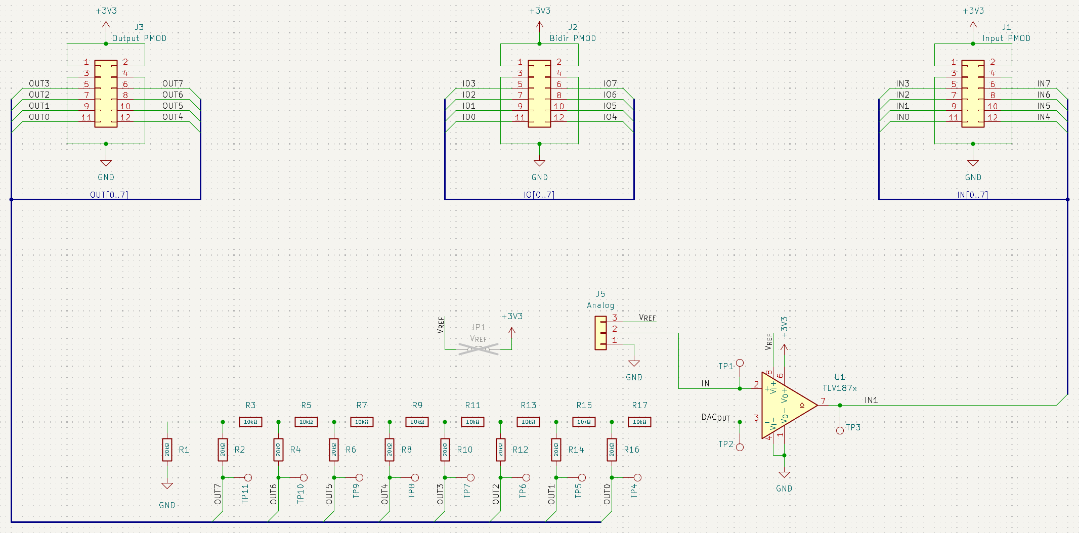
You need to connect a R-2R ladder network to the DAC outputs (uo0 to uo7) of the design.
The output of this DAC has to be input into the negative comparator input, where the positive comparator input would be the input voltage.
The output of this comparator would then connect to the comp_i input (ui1) of the design.
The circuit could look something like this:
IO
| # | Input | Output | Bidirectional |
|---|---|---|---|
| 0 | start_i | dac0_o | result0_o |
| 1 | comp_i | dac1_o | result1_o |
| 2 | dac2_o | result2_o | |
| 3 | dac3_o | result3_o | |
| 4 | dac4_o | result4_o | |
| 5 | dac5_o | result5_o | |
| 6 | dac6_o | result6_o | |
| 7 | dac7_o | result7_o |