454 TinyQV SoC with additional peripherals
454 : TinyQV SoC with additional peripherals
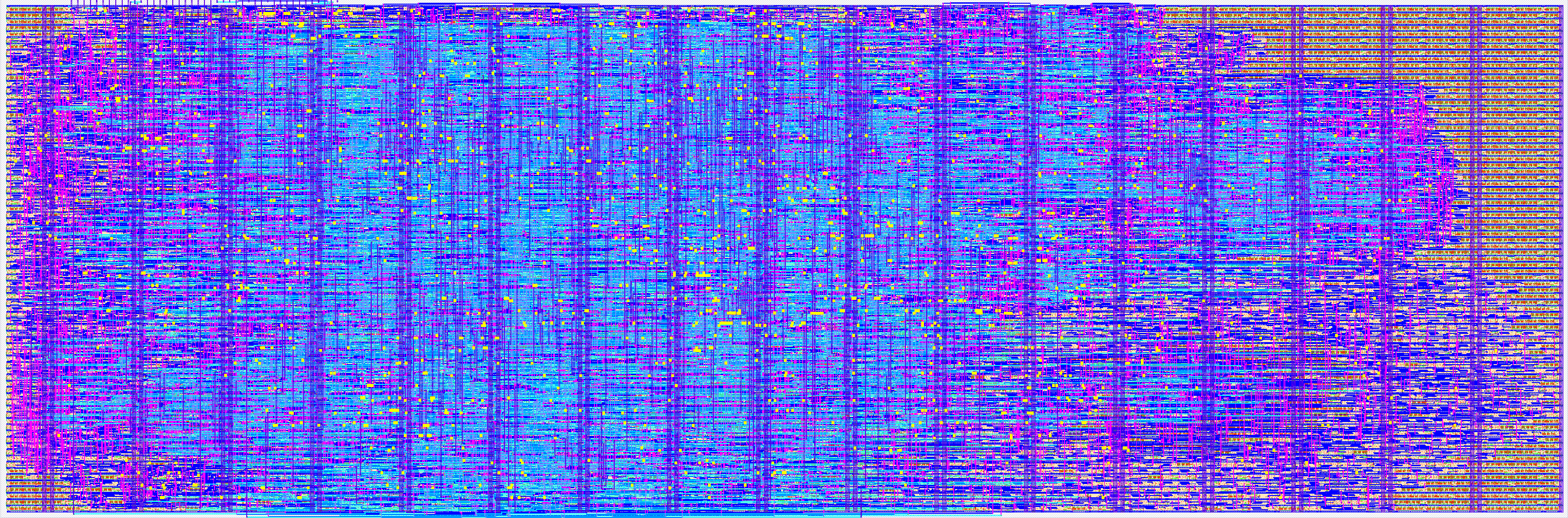
- Author: Michael Bell
- Description: A Risc-V SoC with Tiny Tapeout contributed peripherals
- GitHub repository
- Open in 3D viewer
- Open in Tiny Tapeout Explorer
- Clock: 64000000 Hz
How it works
TinyQV is a small Risc-V SoC, implementing the RV32EC instruction set plus the Zcb and Zicond extensions, with a couple of caveats:
- Addresses are 28-bits
- Program addresses are 24-bits
- gp is hardcoded to 0x1000400, tp is hardcoded to 0x8000000.
Instructions are read using QSPI from Flash, and a QSPI PSRAM is used for memory. The QSPI clock and data lines are shared between the flash and the RAM, so only one can be accessed simultaneously.
Code can only be executed from flash. Data can be read from flash and RAM, and written to RAM.
This version of the SoC is designed to integrate with many user peripherals.
Address map
| Address range | Device |
|---|---|
| 0x0000000 - 0x0FFFFFF | Flash |
| 0x1000000 - 0x17FFFFF | RAM A |
| 0x1800000 - 0x1FFFFFF | RAM B |
| 0x8000000 - 0x8000033 | DEBUG |
| 0x8000034 - 0x800003B | TIME |
| 0x8000040 - 0x800007F | GPIO |
| 0x8000080 - 0x80000FF | UART (user peripherals 0-1) |
| 0x8000100 - 0x80003FF | User peripherals 2-13 |
| 0x8000400 - 0x80004FF | Simple user peripherals 0-15 |
DEBUG
| Register | Address | Description |
|---|---|---|
| SEL | 0x800000C (R/W) | Bits 6-7 enable peripheral output on the corresponding bit on out6-7, otherwise out6-7 is used for debug. |
| DEBUG_UART_DATA | 0x8000018 (W) | Transmits the byte on the debug UART |
| STATUS | 0x800001C (R) | Bit 0 indicates whether the debug UART TX is busy, bytes should not be written to the data register while this bit is set. |
See also debug docs
TIME
| Register | Address | Description |
|---|---|---|
| MTIME | 0x8000034 (RW) | Get/set the 1MHz time count |
| MTIMECMP | 0x8000038 (RW) | Get/set the time to trigger the timer interrupt |
GPIO
| Register | Address | Description |
|---|---|---|
| OUT | 0x8000040 (RW) | Control for out0-7 if the GPIO peripheral is selected |
| IN | 0x8000044 (R) | Reads the current state of in0-7 |
| FUNC_SEL | 0x8000060 - 0x800007F | Function select for out0-7 |
| Function Select | Peripheral |
|---|---|
| 0 | Disabled |
| 1 | GPIO |
| 2 | UART TX |
| 3 | UART RX |
| 4 - 15 | User peripheral 2-13 |
| 16 | Edge counter |
| 17 - 31 | Simple user peripheral 1-15 |
UART
| Register | Address | Description |
|---|---|---|
| TX_DATA | 0x8000080 (W) | Transmits the byte on the UART |
| TX_BUSY | 0x8000084 (R) | Bit 0 indicates whether the UART TX is busy, bytes should not be written to the data register while this bit is set. |
| RX_DATA | 0x80000C0 (R) | Reads any received byte |
| RX_STATUS | 0x80000C4 (R) | Bit 0 indicates whether a received byte is available to be read. |
Edge Counter
The edge counter is simple peripheral 0, with base address 0x8000400.
How to test
Load an image into flash and then select the design.
Reset the design as follows:
- Set rst_n high and then low to ensure the design sees a falling edge of rst_n. The bidirectional IOs are all set to inputs while rst_n is low.
- Program the flash and leave flash in continuous read mode, and the PSRAMs in QPI mode
- Drive all the QSPI CS high and set SD1:SD0 to the read latency of the QSPI flash and PSRAM in cycles.
- Clock at least 8 times and stop with clock high
- Release all the QSPI lines
- Set rst_n high
- Set clock low
- Start clocking normally
Based on the observed latencies from tt06 testing, at the target 64MHz clock a read latency of 2 is required. The maximum supported latency is currently 3.
The above should all be handled by some MicroPython scripts for the RP2040 on the TT demo PC.
Build programs using the riscv32-unknown-elf toolchain and the tinyQV-sdk, some examples are here.
External hardware
The design is intended to be used with this QSPI PMOD on the bidirectional PMOD. This has a 16MB flash and 2 8MB RAMs.
The UART is on the correct pins to be used with the hardware UART on the RP2040 on the demo board.
The SPI controller is intended to make it easy to drive an ST7789 LCD display (more details to be added).
It may be useful to have buttons to use on the GPIO inputs.
IO
| # | Input | Output | Bidirectional |
|---|---|---|---|
| 0 | Interrupt 0 | UART TX | Flash CS |
| 1 | Interrupt 1 | UART RTS | SD0 |
| 2 | SD1 | ||
| 3 | 1 MHz clock for time | SCK | |
| 4 | SD2 | ||
| 5 | SD3 | ||
| 6 | Debug UART TX | RAM A CS | |
| 7 | UART RX | Debug signal / PWM | RAM B CS / PWM |