452 PolyWave
452 : PolyWave
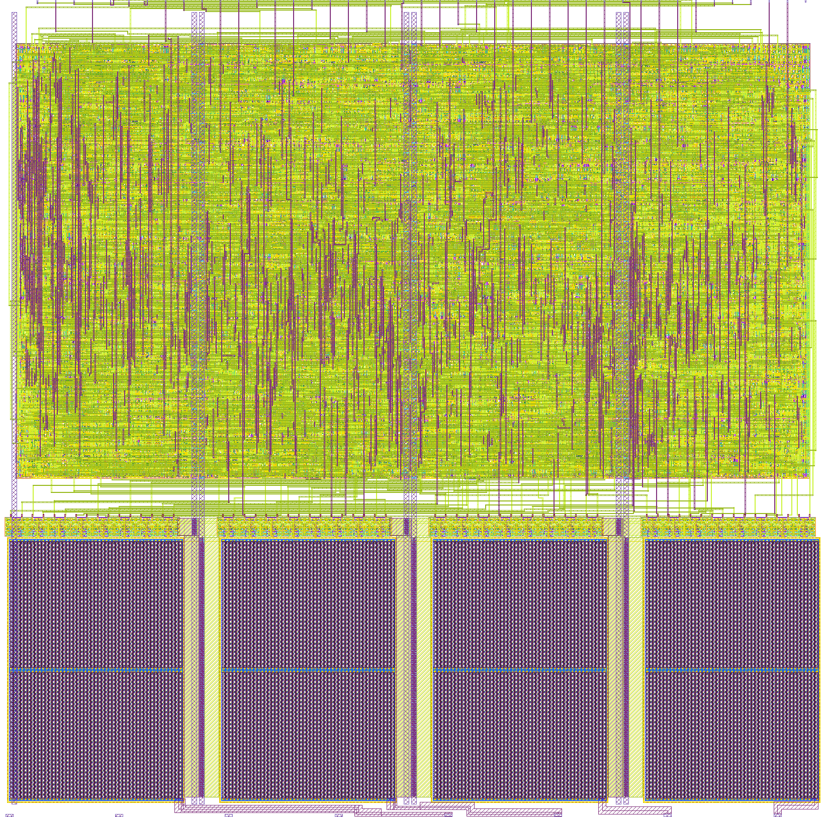
- Author: Riccardo Pellegrini
- Description: Mixed-signal four-channel waveform source with a compact digital engine driving four 16-bit R-2R DACs.
- GitHub repository
- Open in 3D viewer
- Open in Tiny Tapeout Explorer
- Clock: 50000000 Hz
PolyWave
PolyWave is a four-channel mixed-signal waveform source. A compact digital engine generates four 16-bit sample streams, and the custom GF180 layout converts those streams to analog voltages with four R-2R DAC ladders.
The design is intended as a small multi-output waveform lab for synchronized signals, modulation experiments, DAC characterization and mixed-signal Tiny Tapeout demonstrations.
How it works
The digital engine contains four 20-bit phase accumulators, a shared 16-bit LFSR/noise source, a 4-bit sequencer and four 16-bit DAC sample registers. It can run autonomously in generated-waveform mode, or it can accept direct byte writes to any DAC channel.
The four DAC sample registers drive inverted 16-bit layout buses named
R2R_Bn_0, R2R_Bn_1, R2R_Bn_2 and R2R_Bn_3. These buses feed the four
physical R-2R ladders in the custom GDS. The analog DAC outputs are exposed on
ua[0] to ua[3].
This repository uses the Tiny Tapeout custom GDS path. The prebuilt gds/ and
lef/ files are the physical source for the submitted layout. src/project.v
documents and syntax-checks the mixed-signal partition used by the layout; it is
not synthesized by the submission action into a new layout. The public
tt_um_odgrip_polywave module keeps the standard Tiny Tapeout analog port list,
instantiates polywave_top_digital for the digital waveform engine, and
instantiates polywave_top_analog_stub as the analog boundary that represents
the custom GDS. The R-2R buses are internal signals between those two blocks,
not top-level ports.
The submitted analog frame uses the GF180 pgvaa Tiny Tapeout interface, so
VAPWR remains part of the project interface even though the current digital
engine does not consume the analog supply internally.
Digital controls
Generated mode
Set ui_in[7] low to use the autonomous waveform generator.
| Signal | Function |
|---|---|
ui_in[2:0] |
Extra live modulation bits and low-cost phase nudges |
ui_in[3] |
Fast internal tempo select |
ui_in[5:4] |
Scene selection for the waveform formulas |
ui_in[6] |
Freeze phase accumulator updates while held high |
uio_in[7:0] |
Live modulation/control bus used by the waveform engine |
In this mode the four phase accumulators, cross-modulation paths, sequencer, noise source, saw/triangle/PWM/stepped waveforms and live controls generate the four DAC values.
Direct DAC mode
Set ui_in[7] high to stop generated DAC updates and write DAC codes directly.
| Signal | Function |
|---|---|
ui_in[5:4] |
DAC channel select: 0 to 3 |
ui_in[3] |
Byte select: 0 for low byte, 1 for high byte |
uio_in[7:0] |
Byte value to load |
ui_in[6] |
Rising-edge load strobe |
To write a full 16-bit DAC code, load the low byte and high byte separately with
two pulses on ui_in[6].
Outputs
| Signal | Function |
|---|---|
ua[0] |
DAC A analog output |
ua[1] |
DAC B analog output |
ua[2] |
DAC C analog output |
ua[3] |
DAC D analog output |
uo_out[2:0] |
Mirror of ui_in[2:0] live modulation bits |
uo_out[6:3] |
Current 4-bit sequencer step |
uo_out[7] |
Tempo tick |
uio_out[7:0] |
Always zero |
uio_oe[7:0] |
Always zero, so the bidirectional pins are input-only controls |
How to test
- Apply power to the design.
- Provide the system clock and release reset.
- Hold
ui_in[7]low for generated-waveform mode. - Observe
ua[0]toua[3]with an oscilloscope or data acquisition system. - Change
ui_in[5:4],ui_in[3],ui_in[2:0]anduio_in[7:0]to exercise the live waveform controls. - Set
ui_in[7]high and use direct DAC mode to write known 16-bit codes to each channel. - Check
uo_out[7]anduo_out[6:3]for the tempo tick and sequencer state.
External hardware
Use a clock/reset source, digital control source for ui_in and uio_in, and an
oscilloscope, logic analyzer or data acquisition system to observe the analog and
status outputs.
IO
| # | Input | Output | Bidirectional |
|---|---|---|---|
| 0 | MOD0 | MOD0_MON | LIVE0 |
| 1 | MOD1 | MOD1_MON | LIVE1 |
| 2 | MOD2 | MOD2_MON | LIVE2 |
| 3 | TEMPO_HI | SEQ0 | LIVE3 |
| 4 | SCENE0 | SEQ1 | LIVE4 |
| 5 | SCENE1 | SEQ2 | LIVE5 |
| 6 | FREEZE/LOAD | SEQ3 | LIVE6 |
| 7 | DIRECT | TEMPO_TICK | LIVE7 |
Analog pins
ua | PCB Pin | Internal index | Description |
|---|---|---|---|
| 0 | J | 4 | DAC_A |
| 1 | D | 1 | DAC_B |
| 2 | G | 3 | DAC_C |
| 3 | F | 2 | DAC_D |