37 algofoogle analog stuff
37 : algofoogle analog stuff
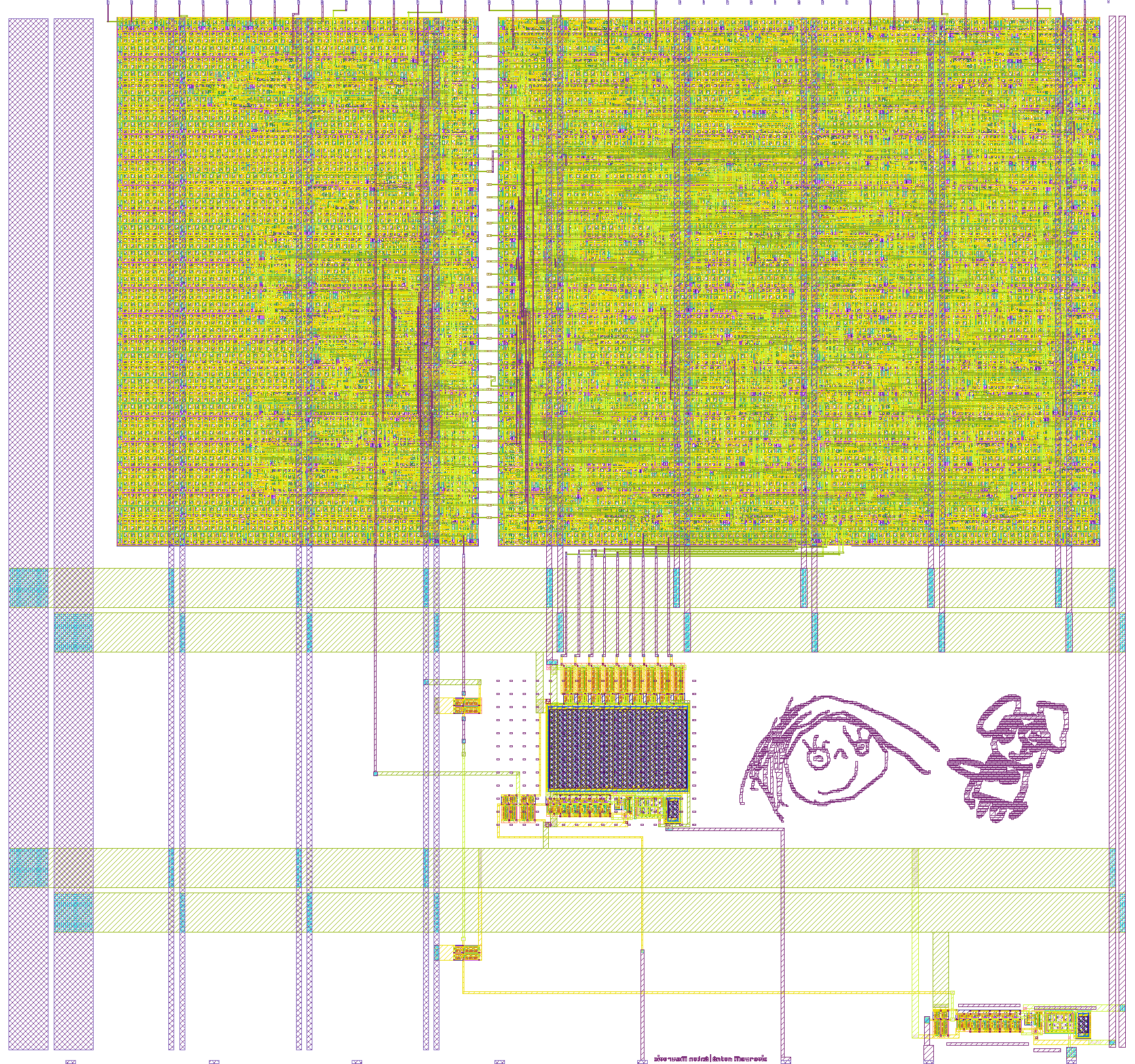
- Author: algofoogle (Anton Maurovic)
- Description: Some analog and custom layout experiments in gf180mcuD for ttgf0p3 (the TT GF 1st analog experimental shuttle)
- GitHub repository
- Open in 3D viewer
- Open in Tiny Tapeout Explorer
- Open in VGA Playground
- Clock: 0 Hz
How it works
This is a simple VCO experiment using a current-starved ring oscillator. It consists of 5 current-starved inverter stages in a ring, followed by a buffer pair. This is output via ua[1] and also fed to a digital test block where it is divided using a 5-bit synchronous counter and presented on uio_out[5:1], beside a buffered (but non-divided) copy of the VCO output on uio_out[0] (aka osc_out).
For a given input voltage (vin, i.e. ua[0]) in the range 0.55V to 3.3V, the oscillator output (vco_out, i.e. ua[1]) is expected to be a square wave roughly in the range of 2MHz to 400MHz.
How to test
- Apply power with
vinheld at 0V andrst_nhigh. No TTclkis required. Expect to see no oscillation onvco_outoruio_out[5:1]. - Raise
vinto 0.55V, and you might seevco_outoscillating at about 2MHz, 3.3Vpp, about 50% duty cycle. - Raise
vinslowly and ifvco_outwasn't already oscillating then you should see it start at least by the timevinreaches 0.65V (if not sooner), and as you raisevinfurther the frequency atvco_outshould rapidly increase. - Observe digital-buffered (and TT-digital-mux-shaped) output of the VCO on
uio_out[0], and then halving of the frequency up through each ofuio_out[1]touio_out[5].
External hardware
- Precision variable voltage source for
vin. - Oscilloscope to monitor
vco_out.
IO
| # | Input | Output | Bidirectional |
|---|---|---|---|
| 0 | dac_d0 | R1 | avo[0] |
| 1 | dac_d1 | G1 | avo[1] |
| 2 | dac_d2 | B1 | avo[4] |
| 3 | dac_load | VSync | avo[5] |
| 4 | dac_shift | R0 | dvo[0] |
| 5 | vco_disable | G0 | dvo[1] |
| 6 | test_mode | B0 | dvo[4] |
| 7 | vga_mode | HSync | dvo[5] |
Analog pins
ua | PCB Pin | Internal index | Description |
|---|---|---|---|
| 0 | 12 | ana_vco_vin | |
| 1 | 13 | ana_vco_out | |
| 2 | 14 | dac_vco_vin | |
| 3 | 15 | dac_vco_out |