193 SPI test
193 : SPI test
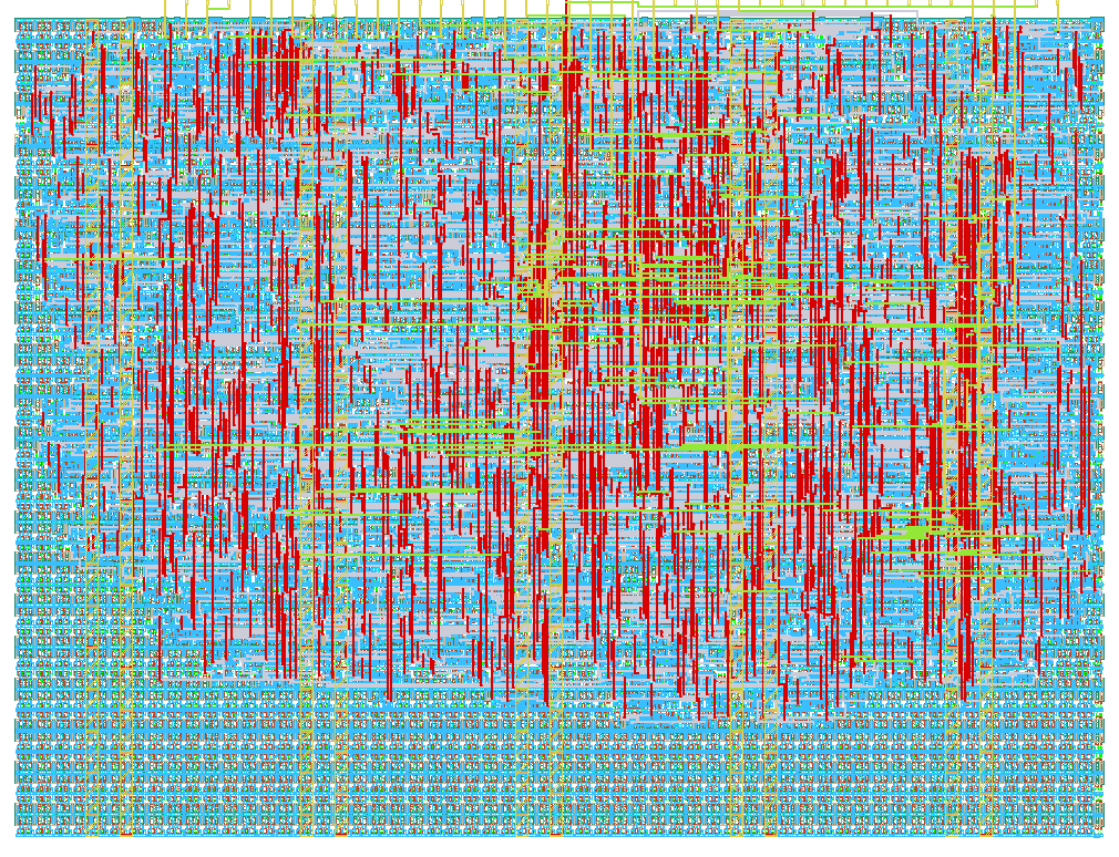
- Author: Caio Alonso da Costa
- Description: SPI test
- GitHub repository
- Open in 3D viewer
- Open in Tiny Tapeout Explorer
- Clock: 50000000 Hz
How it works
SPI test design based from https://github.com/calonso88/tt07_alu_74181
See that design's docs for information about the SPI peripheral.
Small improvement done on the spi_reg module. There used to be two buffer counters (one for RX and one for TX). Since the counters are not used together, it was possible to remove one of them and use a single buffer counter. This has reduced 4 flip flops in total and some combinatorial logic as well.
Added logic to control driver for MISO. On previous submissions of this design, the MISO was always driven. Logic has been added to put MISO into high impedance when CS_N is driven high. Due to a 2-stage synchronizer, the MISO goes to high impedance after 2 clock cycles.
Design been configured with 8 read/write 8 bit registers and 8 read only 8 bit status registers.
The first read/write register also drives the 7 segment display.
How to test
Use SPI1 Master peripheral in RP2040 to start communication on SPI interface towards this design. Remember to configure the SPI mode using the switches in DIP switch (if you'd like to have CPOL=1 and CPHA=1). Alternatively, don't use the DIP switches and use the RP2040 GPIOs to configure the SPI mode in the desired mode.
Example code to initialize SPI in REPL:
spi_miso = tt.pins.pin_uio3
spi_cs = tt.pins.pin_uio4
spi_clk = tt.pins.pin_uio5
spi_mosi = tt.pins.pin_uio6
spi_miso.init(spi_miso.IN, spi_miso.PULL_DOWN)
spi_cs.init(spi_cs.OUT)
spi_clk.init(spi_clk.OUT)
spi_mosi.init(spi_mosi.OUT)
spi = machine.SoftSPI(baudrate=10000, polarity=0, phase=0, bits=8, firstbit=machine.SPI.MSB, sck=spi_clk, mosi=spi_mosi, miso=spi_miso)
spi_cs(1)
Example code to write 0xF8 to address[0]:
spi_cs(0); spi.write(b'\x80\xF8'); spi_cs(1)
This should set the 7 segment LED to 0xF8 which will display "t."
Seg A - OFF, Seg B - OFF, Seg C - OFF, Seg D - ON, Seg E - ON, Seg F - ON, Seg G - ON, Seg DP - ON
Example code to read from address[0]:
spi_cs(0); spi.write(b'\x00'); spi.read(1); spi_cs(1)
The result should be 0xF8 or whatever you wrote to address[0].
External hardware
Not required. Write to the first register to set the LEDs on the demoboard.
External hardware
None.
IO
| # | Input | Output | Bidirectional |
|---|---|---|---|
| 0 | cpol | spare[0] | |
| 1 | cpha | spare[1] | |
| 2 | spare[2] | ||
| 3 | spare[3] | spi_miso | |
| 4 | spare[4] | spi_cs_n | |
| 5 | spare[5] | spi_clk | |
| 6 | spare[6] | spi_mosi | |
| 7 | spare[7] |