0 Chip ROM
0 : Chip ROM
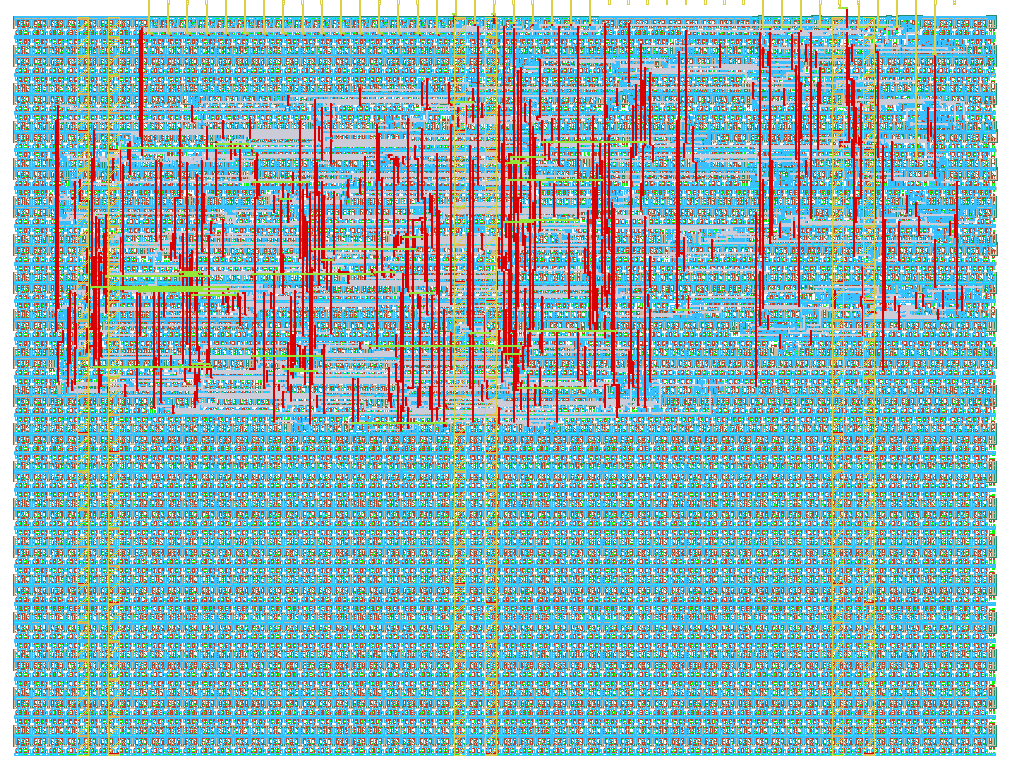
- Author: Uri Shaked
- Description: ROM with information about the chip
- GitHub repository
- Open in 3D viewer
- Open in Tiny Tapeout Explorer
- Clock: 0 Hz
How it works
ROM memory that contains information about the Tiny Tapeout chip. The ROM is 8-bit wide and 256 bytes long.
The ROM layout
The ROM layout is as follows:
| Address | Length | Encoding | Description |
|---|---|---|---|
| 0 | 8 | 7-segment | Shuttle name (e.g. "tt07"), null-padded |
| 8 | 8 | 7-segment | Git commit hash |
| 32 | 96 | ASCII | Chip descriptor (see below) |
| 248 | 4 | binary | Magic value: "TT\xFA\xBB" |
| 252 | 4 | binary | CRC32 of the ROM contents, little-endian |
The chip descriptor
The chip descriptor is a simple null-terminated string that describes the chip. Each line is a key-value pair, separated by an equals sign. It contains the following keys:
| Key | Description | Example value |
|---|---|---|
| shuttle | The identifier of the shuttle | tt07 |
| repo | The name of the repository | TinyTapeout/tinytapeout-07 |
| commit | The commit hash * | a1b2c3d4 |
* The commit hash is only included for Tiny Tapeout 5 and later.
Here is a complete example of a chip descriptor:
shuttle=tt07
repo=TinyTapeout/tinytapeout-07
commit=a1b2c3d4
How the ROM is generated
The ROM is automatically generated by tt-support-tools
while building the final GDS file of the chip. Look at the rom.py file in the repository for more details.
Reading the ROM
There are two ways to address ROM, depending on the value of the rst_n pin:
- When
rst_nis high: Set theui_inpins to the desired address. - When
rst_nis low: Toggle theclkpin to read the ROM contents sequentially, starting from address 0.
In both cases, the ROM data for the selected address will be available on the uo_out pins, one byte at a time.
How to test
The first 16 bytes of the ROM are 7-segment encoded and contain the shuttle name and commit hash. You can dump them by holding rst_n low and toggling the clk pin, and observing the on-board 7-segment display.
Alternatively, you can keep rst_n high and set the ui_in pins to the desired address using the first four on-board DIP switches, while observing the on-board 7-segment display.
IO
| # | Input | Output | Bidirectional |
|---|---|---|---|
| 0 | addr[0] | data[0] | |
| 1 | addr[1] | data[1] | |
| 2 | addr[2] | data[2] | |
| 3 | addr[3] | data[3] | |
| 4 | addr[4] | data[4] | |
| 5 | addr[5] | data[5] | |
| 6 | addr[6] | data[6] | |
| 7 | addr[7] | data[7] |