590 ROM-less Cordic Engine
590 : ROM-less Cordic Engine
- Author: Rohan Sundar, Rohan Verma and Jyotinder Singh
- Description: A ROM-less cordic engine that utilizes SPI-slave interface to receive four 16-bit inputs (atan₀, alpha, x, y) and returns three 16-bit outputs (alpha, cosθ, sinθ).
- GitHub repository
- Open in 3D viewer
- Clock: 50000000 Hz
Credits
The development of this ROM-less CORDIC engine was made possible by the engineering team at Vicharak, who contributed subject matter expertise in math and RTL synthesis. Their Vaaman development platform served as an effective test harness for validating RTL designs and verifying algorithms.
Devang Kabutarwala, Kasetty Praveen Kumar, Rishik Ram Jallarapu, Deepak Sharda, Tejas Dabhankar, Akshar Vastarpara
How it works
Cordic-16 is a ROM-less CORDIC implementation with 16-bit signed fixed-point input Q3.16 (1 sign bit, 3 integer bits, and 12 fraction bits). This core comprises mainly (i) a single-stage CORDIC engine that operates in rotation mode for computing $cos$ and $sin$ of input angle $\theta$, and (ii) an $arctan$ generator that generates the micro-rotation angles dynamically in each clock cycle for the corresponding iteration.
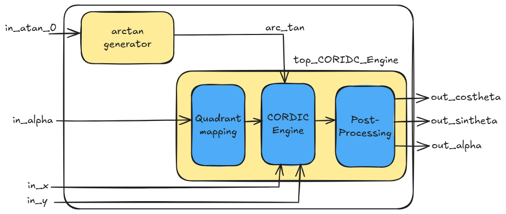
The aforementioned CORDIC core accepts the input angle $\theta$ in radian format; since $\theta \in [0, 2\pi]$, 3 bits are sufficient to accommodate the integer part of the angle and 12 bits for the fractional part to achieve accuracy. Hence, 16-bit data width is chosen, and the CORDIC engine is iterated over 13 iterations. In this implementation, the micro-rotation angles $arctan$ were generated using Taylor series approximation to avoid the memory for storing them.
Basic Functionality of CORDIC CORE
The CORDIC core computes trigonometric functions by rotating a vector iteratively by breaking down the angle of rotation into a set of small predefined angles. If a two-dimensional vector $v_0=[x_0,y_0]$ is rotated by an angle $\theta$, then it results in a vector $v_L=[x_L,y_L]$. The rotation angle $\theta$ is expressed as a series of $L$ micro-rotation angles $\alpha_i = \arctan(2^{-i})$ as shown below.
$\theta = \sum_{i=0}^{L-1}\sigma_i\alpha_i, ~i=0,1,2,\cdots L-1$
where, $\sigma_i=\pm1$ controls the direction of the micro-rotation. In each iteration, the vector is rotated with elementary angle $\alpha_i$ as follows,
$x_{i+1} = x_i-\sigma_i2^{-i}y_i$
$y_{i+1} = y_i+\sigma_i2^{-i}x_i$
$z_{i+1} = z_i-\sigma_i\alpha_i$
where $z_i$ corresponds to the rotation angle in the $i^{th}$ iteration and $z_0$ is the initial angle. In rotation mode, $\sigma_i = \text{sign}(z_i)$. The basic architecture for the implementation of the CORDIC core can be found in the references given at the end of this documentation.
Note that the CORDIC core performs rotation only in Quadrants 1 and 4 (Q1 & Q4), i.e., $\theta \in [-pi/4 , pi/4]$. If input angle lies in Q2 or Q3, then it should be mapped into either Q1 or Q4 and post-processed with the CORDIC output as follows:
| Quadrant | $cos(\theta)$ | $sin(\theta)$ |
|---|---|---|
| Q1 | cos_output_CORDIC | sin_output_CORDIC |
| Q2 | -sin_output_CORDIC | cos_output_CORDIC |
| Q3 | -cos_output_CORDIC | -sin_output_CORDIC |
| Q4 | sin_output_CORDIC | -cos_output_CORDIC |
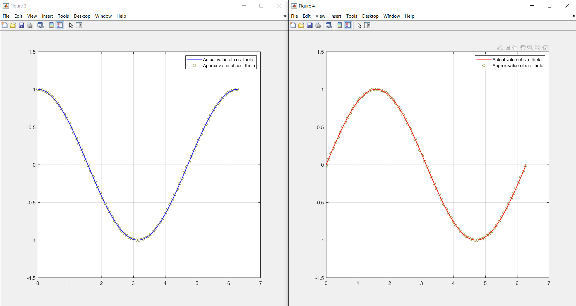
As said, micro-rotation angles were generated using Taylor's series approximation; it is found that the mean absolute error between actual and computed value is $0.003$ for $1000$ samples. This was evaluated using MATLAB; the below figure shows the approximation of the computed value over the actual results.
How to test
The CORDIC is interfaced using SPI, and one byte is transferred at a time. The core expects 8 bytes (64-bit input) as {in_atan_0, in_alpha, in_x, in_y}, where in each of the inputs has a data width of 16 bits. After receiving these inputs, the engine generates the output as {out_alpha, out_costheta, out_sintheta}, wherein each of them is 16 bits. Thus, we receive a total of 6 bytes from SPI.
Here
| Signal name | Details |
|---|---|
| in_y | scaled y-coordinate of input vector (0 in case of calculation of sin calculation) |
| in_x | scaled x-coordinate of input vector |
| in_alpha | input angle in radian |
| in_atan_0 | initial micro-rotation angle |
| out_sintheta | output $cos(\theta)$ value |
| out_costheta | output $sin(\theta)$ value |
| out_alpha | output converged value of input angle (0 in case of sin and cos calculation) |
External hardware
Externally an SPI master is required to communicate and send the input data to the CORDIC.
We have used RP2040 (Pico) for all our testing.
Reference
A lot more about cordic can be understood from this paper
IO
| # | Input | Output | Bidirectional |
|---|---|---|---|
| 0 | ui_in[0] | uo_out[0] | |
| 1 | ui_in[1] | uo_out[1] | |
| 2 | ui_in[2] | ||
| 3 | |||
| 4 | |||
| 5 | |||
| 6 | |||
| 7 |