320 Tiny Tapeout Chirp Modulator
320 : Tiny Tapeout Chirp Modulator
- Author: M. R.
- Description: This digital circuit will accept a UART input Byte and produce a parallel bus output with a chirp waveform for that Byte
- GitHub repository
- Open in 3D viewer
- Clock: 10000000 Hz
How it works
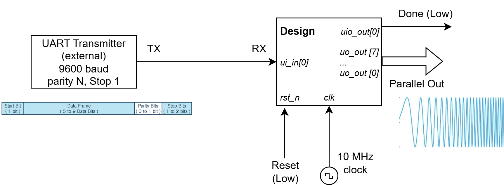
This design will take as input a Byte from a UART receive (RX) line and produce a chirp signal in output. The Chirp is available as 8-bit digital bus (7 is MSB, 0 is LSB). The produced chirp will be the digital rapresentation of the input Byte in LoRa - Style modulation at BW 125 kHz, SF8.
How to test
- Connect all Hardware.
- Connect and enable the 10 MHz clock stimulus.
- Power on: assert Reset input low.
- Send a UART byte and observe the data output.
External hardware
- UART transceiver (TX only) -> connect to input RX
- Clock generator --> connect to clock input (10 MHz clock)
- Digital Signal Analyzer --> connect bit 7 down to 0 of output data
IO
| # | Input | Output | Bidirectional |
|---|---|---|---|
| 0 | UART RX | o_data_0(LSB) | o_done(Chirp Done) |
| 1 | o_data_1 | ||
| 2 | o_data_2 | ||
| 3 | o_data_3 | ||
| 4 | o_data_4 | ||
| 5 | o_data_5 | ||
| 6 | o_data_6 | ||
| 7 | o_data_7(MSB) |