425 8-bit Multiply-Accumulate (MAC) with 2-Cycle Serial Interface
425 : 8-bit Multiply-Accumulate (MAC) with 2-Cycle Serial Interface
- Author: Bryan Kuang
- Description: An 8×8→16-bit multiply-accumulate unit with 2-cycle 8-bit serial interface, supporting signed/unsigned operations with overflow detection and clear functionality
- GitHub repository
- Open in 3D viewer
- Clock: 50000000 Hz
How it works
This project is an 8×8→16‑bit Multiply–Accumulate (MAC) peripheral designed for the TinyTapeout platform. It is ideal for DSP applications or any design requiring efficient, repeated multiplication and addition.
To fit within the limited I/O of TinyTapeout, the MAC core uses a 2‑cycle 8‑bit serial interface. This allows two 8-bit operands to be sent to the core and a full 16‑bit result to be read back, all through a standard 8-bit data bus. The module also supports configurable signed/unsigned arithmetic and provides overflow detection.
Key Features
- Compact MAC Core: Provides a full 8x8 MAC unit with a 17-bit accumulator and overflow detection.
- 2-Cycle Serial Interface: A simple 2‑cycle input/output protocol allows full 16-bit operations using only 8-bit data ports, making it easy to integrate with microcontrollers or other hosts.
- Signed/Unsigned Support: A dedicated control pin (
signed_mode) allows switching between signed and unsigned arithmetic. - High-Speed Operation: Maintains full 50 MHz operation with a deterministic 4‑cycle pipeline latency.
Architecture
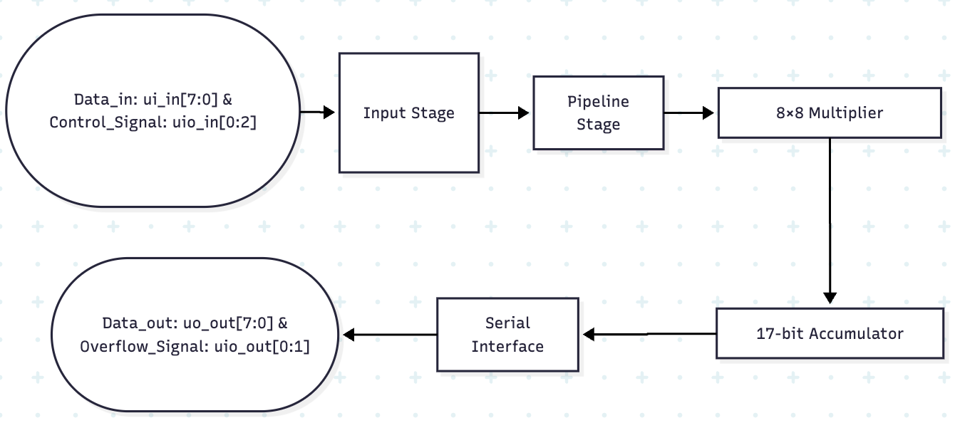
The peripheral's architecture is a 4-stage pipeline designed for stable, high-speed operation:
- Input Stage & Serial Interface: Captures and assembles the two 8‑bit operands and control signals over two clock cycles. A change detector triggers the pipeline only when new, stable data is available.
- Pipeline Register Stage: Registers the inputs for timing closure and passes the
signed_modesetting to the multiplier and accumulator. - Multiplier Stage: A configurable 8×8 block that produces a 16‑bit product, supporting both signed and unsigned modes.
- Accumulator Stage: A 17‑bit adder with
clear_and_multcontrol. It accumulates results and sets an overflow flag if the result exceeds the 16-bit range.
Pinout
| Pin | Direction | Function |
|---|---|---|
ui_in[7:0] |
Input | 8-bit Data Bus. Used for Data A (cycle 1) and Data B (cycle 2). |
uio_in[0] |
Input | clear_and_mult (0 = accumulate, 1 = clear before multiplying) |
uio_in[1] |
Input | enable (Must be high during the 2-cycle input phase) |
uio_in[2] |
Input | signed_mode (0 = unsigned, 1 = signed) |
uo_out[7:0] |
Output | 8-bit Data Bus. Cycles between the high and low bytes of the 16-bit result. |
uio_out[0] |
Output | overflow flag (High when an arithmetic overflow occurs) |
uio_out[1] |
Output | data_ready flag (High when a new result is available) |
How to Use the MAC
Operating the MAC involves sending two 8-bit operands and control signals over two clock cycles, waiting for the pipeline to process, and then reading the 16-bit result over two subsequent cycles.
Data Transmission Protocol
Input Protocol (2 cycles):
- Cycle 1:
- Place 8-bit Data A on
ui_in[7:0]. - Set
uio_in[1]to1to enable the interface. - Set
uio_in[0](clear_and_mult) anduio_in[2](signed_mode) as needed. These values are only captured on the first cycle.
- Place 8-bit Data A on
- Cycle 2:
- Place 8-bit Data B on
ui_in[7:0]. - Keep
uio_in[1](enable) at1.
- Place 8-bit Data B on
- After Cycle 2, set
uio_in[1](enable) to0to complete the input operation.
Output Protocol (2 cycles):
- After an operation is complete (approx. 4-6 cycles), the
data_readyflag (uio_out[1]) will go high. - The 16-bit result is available on
uo_out[7:0]and cycles between the high and low bytes on every clock edge. - Read Cycle 1: Capture the High Byte (bits 15:8) of the result.
- Read Cycle 2: Capture the Low Byte (bits 7:0) of the result.
- The
overflowflag is available onuio_out[0].
Usage Examples
Example 1: Basic Multiplication (5 * 6)
// 1. Send data to calculate 5 * 6 = 30
// Cycle 1: Send Data A (5) and control signals (clear=1, signed=0)
ui_in <= 8'h05;
uio_in <= 3'b011; // {signed_mode, enable, clear_and_mult}

// Cycle 2: Send Data B (6)
ui_in <= 8'h06;
uio_in <= 3'b010; // {signed_mode, enable, clear_and_mult} - only enable matters

// 2. Wait ~4-6 cycles for the pipeline.

// 3. Read the result (30 = 0x001E)
// Read Cycle 1: uo_out will be 0x00 (High Byte)
// Read Cycle 2: uo_out will be 0x1E (Low Byte)
Example 2: Accumulation (100 + 25)
// 1. First, calculate 10 * 10 = 100 with clear_and_mult = 1
// ... send 10 and 10 ...

// 2. Wait for the operation to complete.

// 3. Next, calculate 5 * 5 = 25 with clear_and_mult = 0 to accumulate
// Cycle 1: Send Data A (5) and control signals (clear=0, signed=0)
ui_in <= 8'h05;
uio_in <= 3'b010; // {signed_mode, enable, clear_and_mult}

// Cycle 2: Send Data B (5)
ui_in <= 8'h05;
uio_in <= 3'b010;

// 4. Wait for the pipeline.

// 5. Read the result (125 = 0x007D)
// Read Cycle 1: uo_out will be 0x00 (High Byte)
// Read Cycle 2: uo_out will be 0x7D (Low Byte)
Example 3: Signed Multiplication (10 * -5)
// 1. Send data for 10 * -5 = -50, with signed_mode = 1
//    -5 in 8-bit two's complement is 0xFB (251)
// Cycle 1: Send Data A (10) and control signals (clear=1, signed=1)
ui_in <= 8'h0A;
uio_in <= 3'b111; // {signed_mode, enable, clear_and_mult}

// Cycle 2: Send Data B (251)
ui_in <= 8'hFB;
uio_in <= 3'b110;

// 2. Wait for the pipeline.

// 3. Read the result (-50 = 0xFFCE in 16-bit two's complement)
// Read Cycle 1: uo_out will be 0xFF (High Byte)
// Read Cycle 2: uo_out will be 0xCE (Low Byte)
External hardware
No external hardware is required. This is a purely digital design that operates with:
- Clock: A 50MHz system clock from the TinyTapeout board.
- Reset: An active-low reset signal.
- Digital I/O: The standard TinyTapeout pin interface for sending operands and control signals.
IO
| # | Input | Output | Bidirectional |
|---|---|---|---|
| 0 | Data[7:0] - 8-bit data input (Cycle 1: Data A, Cycle 2: Data B) | Result[7:0] - 8-bit data output (cycles between low/high bytes) | Clear_and_Mult (IN) / Overflow (OUT) - Control input or overflow flag output |
| 1 | Data[7:0] - 8-bit data input (Cycle 1: Data A, Cycle 2: Data B) | Result[7:0] - 8-bit data output (cycles between low/high bytes) | Enable (IN) / Data_Ready (OUT) - Interface enable input or data ready output |
| 2 | Data[7:0] - 8-bit data input (Cycle 1: Data A, Cycle 2: Data B) | Result[7:0] - 8-bit data output (cycles between low/high bytes) | Signed_Mode (IN) - Signed mode control (0=unsigned, 1=signed) |
| 3 | Data[7:0] - 8-bit data input (Cycle 1: Data A, Cycle 2: Data B) | Result[7:0] - 8-bit data output (cycles between low/high bytes) | |
| 4 | Data[7:0] - 8-bit data input (Cycle 1: Data A, Cycle 2: Data B) | Result[7:0] - 8-bit data output (cycles between low/high bytes) | |
| 5 | Data[7:0] - 8-bit data input (Cycle 1: Data A, Cycle 2: Data B) | Result[7:0] - 8-bit data output (cycles between low/high bytes) | |
| 6 | Data[7:0] - 8-bit data input (Cycle 1: Data A, Cycle 2: Data B) | Result[7:0] - 8-bit data output (cycles between low/high bytes) | |
| 7 | Data[7:0] - 8-bit data input (Cycle 1: Data A, Cycle 2: Data B) | Result[7:0] - 8-bit data output (cycles between low/high bytes) |