872 Arbitrary Waveform Generator
872 : Arbitrary Waveform Generator
- Author: Daniel Teal
- Description: Streams waveforms. Needs external R-2R ladder.
- GitHub repository
- Open in 3D viewer
- Clock: 0 Hz
How it works
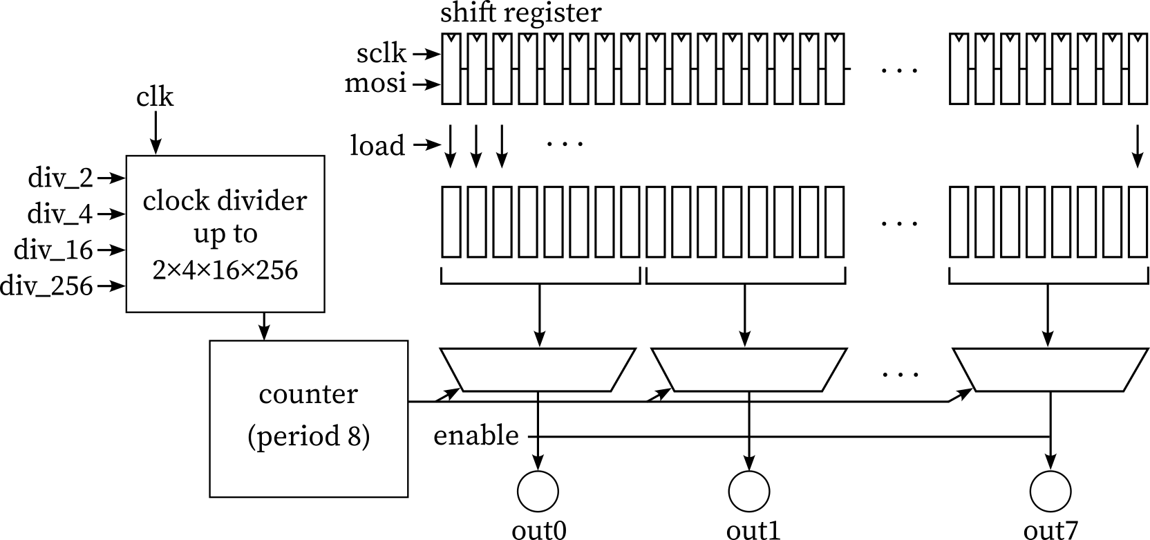
This projects implements a simple streaming arbitrary waveform generator. There are 8 digital output pins which need to be connected to an external R-2R ladder or similar in order to produce an analog waveform. These pins are cycled between 8 states, creating an arbitrary wave.
The data is provided by an external microcontroller via SPI (sclk and mosi, though sclk must be at least 2x slower than clk) into a shift register. The shift register data is loaded into an active register from which the wave is generated when load is high. Note this allows changing data when streaming. Output can be turned on or off with enable.
The output frequency is clk modulo the period 8 output counter, but there are four clock dividers available to slow the output waveform. These are 2x, 4x, 16x, and 256, stackable for up to 32768x division, not including the 8x division of the waveform.
How to test
Ensure rst_n is high and begin by constantly toggling clk at a sufficiently high value (this is required for SPI to work). Next, use sclk and mosi to feed in waveform data equal to the number of time points (8) times the number of output pins (8), i.e., 64 bits total. Once data is loaded, raise the load pin to make the data active, and hold enable high to start output. The provided data should now be shown sequentially on output pins. Optionally hold frequency pins high to divide the clock signal.
External hardware
By itself, this circuit merely toggles its output pins. To create a single analog waveform, some sort of DAC circuitry needs to be attached to the output: an R-2R ladder, a monotonic string / thermometer-coded DAC, or similar.
IO
| # | Input | Output | Bidirectional |
|---|---|---|---|
| 0 | sclk | wave out 0 | n/c |
| 1 | mosi | wave out 1 | n/c |
| 2 | load | wave out 2 | n/c |
| 3 | enable | wave out 3 | n/c |
| 4 | div_2 | wave out 4 | n/c |
| 5 | div_4 | wave out 5 | n/c |
| 6 | div_16 | wave out 6 | n/c |
| 7 | div_256 | wave out 7 | n/c |