812 WobblyBits - A probabilistic computing chip
812 : WobblyBits - A probabilistic computing chip
- Author: Isaac W
- Description: A probabilistic computing array: 6 p-bits driven by a ring-oscillator TRNG, with a SPI-loadable 6x6 coupling matrix for Ising/Boltzmann sampling on SKY130.
- GitHub repository
- Open in 3D viewer
- Clock: 25000000 Hz
How it works
WobblyBits is a probabilistic computing chip. It contains 6 p-bits (probabilistic bits) that fluctuate randomly between 0 and 1 with a probability controlled by their neighbours.
Together the six p-bits form a small Ising/Boltzmann machine: load a coupling matrix over SPI, release the run pin, and the network samples from the encoded probability distribution.
Architecture
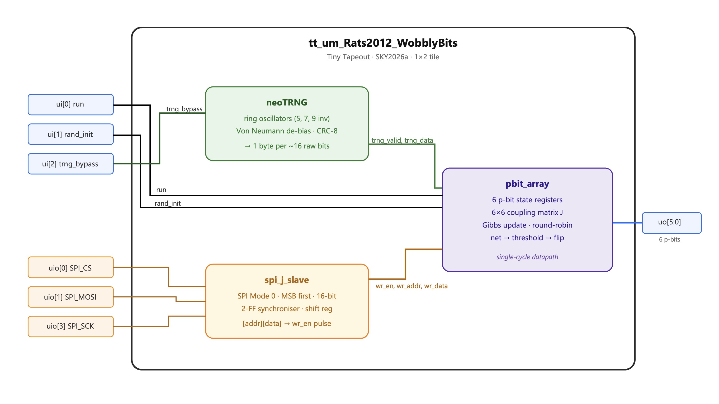
True random number generator
Hardware entropy is provided by the neoTRNG core using three inverter rings (5/7/9 stages XOR-combined).
Each TRNG byte updates one p-bit in round-robin order.
The update rule is a hardware approximation of the sigmoid:
$ \text{net}i = \sum{j \neq i} J[i][j] \cdot (2s_j - 1) $ $ \text{thresh} = \operatorname{clamp}(128 + \text{net}_i,\ 0,\ 255) $ $ s_i^{\text{new}} = \begin{cases} 1 & \text{if } \texttt{trng_byte} < \text{thresh} \ 0 & \text{otherwise} \end{cases} $
thresh maps the net field linearly into a probability: net=0 gives 50/50 probability. Positive values bias toward 1; negative toward 0.
The linear approximation saturates at $ |net| > 127 $.
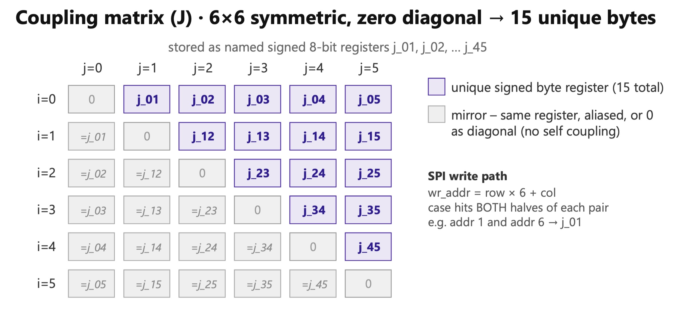
Coupling matrix
The 6×6 coupling matrix has 15 unique off-diagonal entries (the matrix is symmetric; diagonal is 0). These are stored as 8-bit signed registers and accessible via SPI using row-major addressing (addr = 6·row + col).
 {width=60%}
Writing either J[i][j] or J[j][i] updates the same physical register.
Only one register is stored per pair (i,j), reducing storage from 36 to 15 parameters, as otherwise we were struggling to fit on 2 tiles.
Reset default: ferromagnetic K=20 (J[i][j] = 20 for all i≠j). This puts the network near the critical temperature of the all-to-all 6-spin model, giving solid correlated fluctuations out-of-the-box without any SPI configuration.
SPI interface
SPI Mode 0 (CPOL=0, CPHA=0), MSB first. Each transaction is 16 bits: an address byte followed by a data byte.
Address byte layout:
| Bits | Field | Description |
|---|---|---|
addr[7] |
R/W̄ | 0 = write (load J register), 1 = read (return J register on MISO) |
addr[6] |
- | reserved, ignore |
addr[5:0] |
register | matrix entry 0–35 (6·row + col, row-major) |
Write transaction (addr[7]=0): data byte is the 8-bit signed weight to store. Symmetric pairs J[i][j] and J[j][i] alias the same physical register; either address can be written.
Read transaction (addr[7]=1): data byte sent by the master is ignored. The slave shifts out the J register value MSB-first on MISO during the data byte. Use the canonical (lower-row) address for reads: e.g. read J[0][1] at address 1, not address 6. Transposed addresses return 0.
If CS is deasserted mid-frame the partial transaction is silently discarded. The SPI inputs are double-FF synchronised into the 25 MHz system clock domain, limiting SCK to ≈12 MHz (the RP2040 demo board uses ≤4 MHz).
Control and output pins
| Pin | Direction | Function |
|---|---|---|
ui[0] run |
in | 1 = network running, 0 = paused (p-bit updates frozen) |
ui[1] rand_init |
in | 1 = seed p-bit states from TRNG on rising edge of run |
ui[2] trng_bypass |
in | 1 = freeze TRNG and p-bit updates (deterministic simulation) |
uo[5:0] |
out | live p-bit states (pbit0–pbit5) |
uo[6] sweep_done |
out | one-cycle pulse on each completed Gibbs sweep (see below) |
uio[0] SPI_CS |
in | SPI chip select (active low) |
uio[1] SPI_MOSI |
in | SPI data in |
uio[2] SPI_MISO |
out | SPI data out (J register readback) |
uio[3] SPI_SCK |
in | SPI clock |
sweep_done strobe
uo[6] pulses high for exactly one clock cycle each time all six p-bits have completed one full Gibbs sweep (i.e. when the internal round-robin index wraps from 5 back to 0 on a normal update). It does not assert during the rand_init seed byte.
The intended use is as a sample-valid strobe: latch uo[5:0] on the rising edge of uo[6] to accumulate a histogram of states.
Sampling behaviour
The network approximates Boltzmann sampling:
$ P(s) \propto \exp(-E(s)/T) $
with energy
$ E = -\sum_{i<j} J_{ij}s_is_j $
Low-energy states appear most frequently during long observation windows.
How to test
Bring up steps
- Power on with
ui[0](run) = 0 - Load coupling weights via SPI (send
[addr, weight]byte pairs for eachJ[i][j]entry you want to set) - Optionally verify the matrix loaded correctly: read back a few registers using
addr[7]=1(see SPI read protocol above) - Deassert SPI CS, then assert
ui[0]= 1 to start the network - Sample
uo[5:0](p-bit states) on each rising edge ofuo[6](sweep_done) to accumulate a histogram of sweep-aligned samples
No-config smoke test
Without any SPI write, the chip resets to ferromagnetic K=20. Assert run and observe uo[5:0] toggling on each sweep_done pulse.
You should see correlated random fluctuations - all six bits tend to be in the same state (0 or 1) but occasionally flip together. This confirms the TRNG → p-bit datapath is working.
SPI readback verification
Before starting the network, confirm the J matrix loaded correctly. To read J[row][col] set addr[7]=1 and use the canonical (lower-row) address:
addr = 0x80 | (row * 6 + col) where row < col
The slave shifts the 8-bit signed value MSB-first on MISO during the data byte. The master's data byte is ignored. Example: to read J[0][1] send [0x81, 0x00] and capture MISO.
After reset all off-diagonal registers read back +20 (ferromagnetic default).
TRNG quality check
Set J=0 for all entries (fully uncoupled) via SPI. Each p-bit now should fluctuate independently at 50/50.
TRNG bypass (deterministic simulation)
Assert ui[2] = 1 to freeze all updates. Output holds its last value indefinitely. Release to resume.
Ising ground-state test (ferromagnetic)
With default K=20, after sufficient warm-up (a few thousand clock cycles) the network should spend noticeably more time in the all-0 or all-1 states than in mixed states - these are the ferromagnetic ground states.
For stronger alignment: load K=40 via SPI. With K=40 the all-aligned probability is greater.
MAX-CUT demo
Load a K₃,₃ graph (anti-ferromagnetic coupling J=−40 for cross-partition edges 0↔3, 0↔4, 0↔5, 1↔3, 1↔4, 1↔5, 2↔3, 2↔4, 2↔5; J=0 for intra-partition pairs).
The two MAX-CUT ground states are 000111 (pbit0–2 low, pbit3–5 high) and 111000. After warm-up, whichever ground state basin the chain entered will dominate the sample histogram.
These were the RTL results for MAX-CUT K₃,₃ (1000 samples, rand_init=0):
| State | Count | Frac | Cut |
|---|---|---|---|
| 111000 | 445 | 44.5% | 9 ← OPTIMAL |
| 101100 | 142 | 14.2% | 5 |
| 101000 | 89 | 8.9% | 6 |
| 111100 | 73 | 7.3% | 6 |
| others | 251 | 25.1% | ≤5 |
Ground-state (cut=9) fraction: 44.5% vs random baseline 3.1%. Only one ground state observed per run due to symmetry breaking — use rand_init=1 to explore both basins.
Notes
The TRNG uses ring oscillator structures that are experimental and have not been tested in hardware. Timing behaviour is not guaranteed.
IO
| # | Input | Output | Bidirectional |
|---|---|---|---|
| 0 | run | pbit0 | SPI_CS |
| 1 | rand_init | pbit1 | SPI_MOSI |
| 2 | trng_bypass | pbit2 | SPI_MISO |
| 3 | pbit3 | SPI_SCK | |
| 4 | pbit4 | ||
| 5 | pbit5 | ||
| 6 | sweep_done | ||
| 7 |