Tiny Tapeout > Tiny Tapeout Chips > Tiny Tapeout SKY 26a > 774 Design and Implementation of R-2R Ladder DAC for GPR Application
774 Design and Implementation of R-2R Ladder DAC for GPR Application
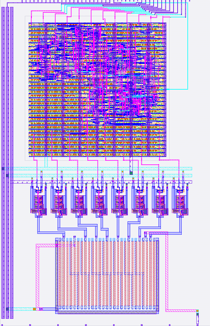
774 : Design and Implementation of R-2R Ladder DAC for GPR Application
- Author: CCCIR_CIT
- Description: A simple 8 bit DAC with a sine waveform driver and 3.3v output
- GitHub repository
- Open in 3D viewer
- Clock: 0 Hz
How it works
It is a 8 bit R2R ladder DAC, which digital signals to analog for GPR Application. The digital signal from the processor is converted and then given to the antenna.
How to test
DAC Test Setup The DAC can be tested using two different modes: External Data Mode and Internal Sawtooth Wave Generator Mode.
- External Data Mode In this mode, the DAC receives digital inputs from an external source. Steps: Set External Data Input = HIGH to enable external data mode. Apply digital values to the 8 input pins of the DAC. Observe the corresponding analog output produced by the DAC.
External hardware
A FPGA board to drive the 8-bit digital inputs.
IO
| # | Input | Output | Bidirectional |
|---|---|---|---|
| 0 | bit 0 | count zero | external data |
| 1 | bit 1 | load divider | |
| 2 | bit 2 | ||
| 3 | bit 3 | ||
| 4 | bit 4 | ||
| 5 | bit 5 | ||
| 6 | bit 6 | ||
| 7 | bit 7 |
Analog pins
ua | PCB Pin | Internal index | Description |
|---|---|---|---|
| 0 | B5 | 11 | DAC output |