35 GF R2R DAC
35 : GF R2R DAC
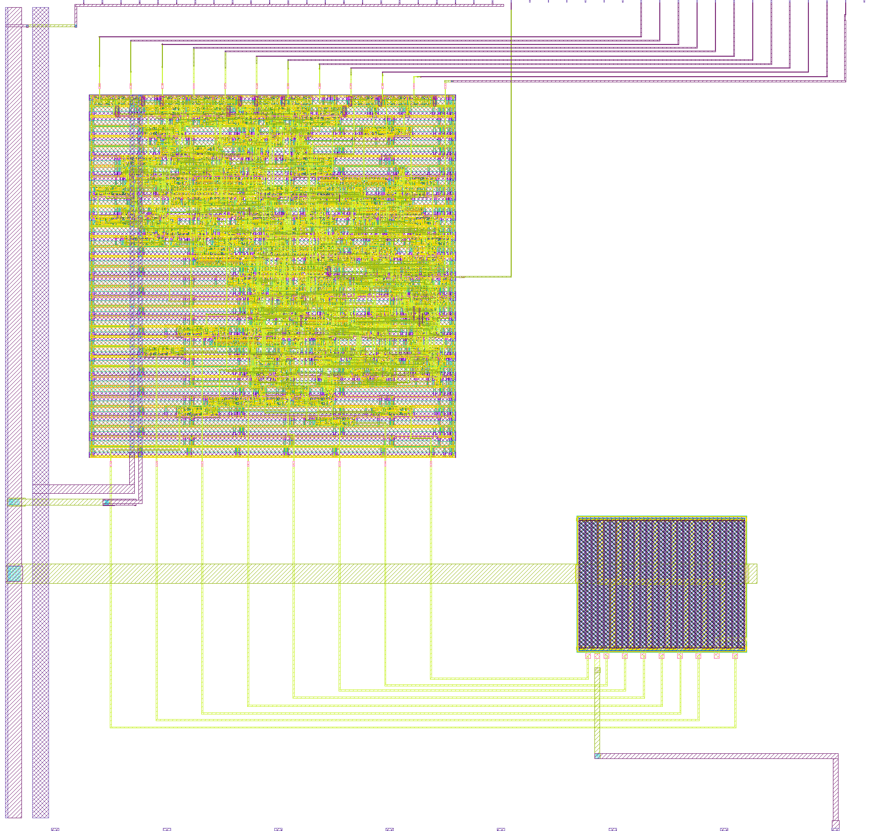
- Author: Matt Venn
- Description: 8 bit R2R DAC
- GitHub repository
- Open in 3D viewer
- Open in Tiny Tapeout Explorer
- Clock: 0 Hz
How it works
A simple 8 bit R2R DAC. Driven externally or by an digitally generated sine waveform generator.
How to test
Drive externally
Set the external data input high to provide the DAC with external data.
Then drive the 8 inputs and observe the analog output.
Drive with internal sine wave generator
Set the external data input low to enable the sine generator.
A sine wave should be seen on the analog output. Everytime the sine counter is at 0, digital output 0 should go high for one clock.
To change the frequency, set the inputs and then raise the 'load divider' input.
External hardware
An oscilloscope to measure the output voltage on analog pin 0.
IO
| # | Input | Output | Bidirectional |
|---|---|---|---|
| 0 | |||
| 1 | |||
| 2 | |||
| 3 | |||
| 4 | |||
| 5 | |||
| 6 | |||
| 7 |
Analog pins
ua | PCB Pin | Internal index | Description |
|---|---|---|---|
| 0 | 15 | output |