106 SotaSoC
106 : SotaSoC
- Author: SotaTek
- Description: RISC-V 32-bit embedded SoC with RV32IC_Zicsr_Zifencei core featuring SPI, I2C, UART, PWM, and GPIO peripherals
- GitHub repository
- Open in 3D viewer
- Clock: 64000000 Hz
How it works
SotaSoC is a compact RISC-V System-on-Chip (SoC) targeting Tiny Tapeout tape-out and also capable of running on Artix 7 FPGA with Vivado. Suitable for custom boards, teaching, and as a base for your own SoC. Software support includes FreeRTOS, MicroPython (in development), and bare-metal.
Supported ISA Extensions
- I — RV32I: 32-bit RISC-V base integer instruction set with 32 general-purpose registers.
- C — RISC-V Compressed instructions.
- Zicsr — Control and Status Register extension.
- Zifencei — Instruction-fetch fence extension.
Peripherals
- QSPI Flash and QSPI PSRAM — 128 Mbit Flash for code and data, 64 Mbit PSRAM for runtime memory
- UART — programmable baud rate via 10-bit clock divider; default 115200 at 64 MHz
- 48-bit timer (mtime)
- 13× GPIO — 1 bidirectional (in/out), 6 input (with interrupt), 6 output
- PWM — 16-bit period and duty (in clock cycles), configurable frequency and duty cycle per channel
- SPI — master; full mode support (CPOL/CPHA), clock up to 16 MHz, configurable; 4-byte buffer
- I2C — master; clock configurable via 8-bit prescaler — 100 kHz, 400 kHz, 1 MHz, and others; START, STOP, repeated START, byte read/write with ACK/NACK
Board Support Package (BSP)
A BSP is available for FreeRTOS and bare-metal development:
- FreeRTOS BSP: https://github.com/sotatek-dev/SotaSoC-BSP/tree/main/examples-freertos
- Bare-Metal BSP: https://github.com/sotatek-dev/SotaSoC-BSP/tree/main/examples-baremetal
Demo
SotaSoC is capable of driving real-world applications such as a 320×240 ST7789 LCD display at ~10 FPS via SPI at 16 MHz clock.
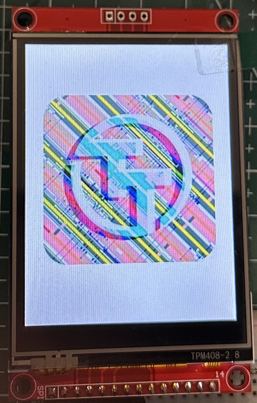
The photo above was taken from a test on an Artix 7 FPGA; the tapeout chip is not yet available.
More examples and demos are available in the SotaSoC-BSP (https://github.com/sotatek-dev/SotaSoC-BSP) repository.
For more detailed technical information, see https://github.com/sotatek-dev/SotaSoC.
How to test
Prerequisites for testing:
- A QSPI Pmod is required.
- System clock is set to 32 MHz.
- Pins ui_in[5] and ui_in[6] are pulled down. These two pins configure the read delay for QSPI data. When the system clock is above 32 MHz, try ui_in[6:5] in order—00, 01, 10, 11—to see which value gives reliable operation. Note: This value is sampled only once, immediately after reset.
Blink
This test verifies the basic functionality of the design by blinking an LED.
-
Write firmware to Flash
Download the blink firmware: https://github.com/sotatek-dev/SotaSoC-BSP/blob/main/examples-baremetal/blink-tt/build/blink-tt.bin, then write it to Flash at address 0x0000_0000.
-
Connect two LEDs to the board
Connect two LEDs (each with a suitable series resistor): one to uo_out[1] and one to uo_out[2].
-
Reset and run
Reset the board. The LED connected to uo_out[2] will blink.
If there is an error related to Flash and PSRAM, the LED connected to uo_out[1] will light up.
ST7789 LCD test
This test verifies the ability to drive the ST7789 LCD via SPI. Follow the instructions below:
-
Write firmware to Flash
Download the firmware from https://github.com/sotatek-dev/SotaSoC-BSP/blob/main/examples-baremetal/spi-st7789-tt/build/spi-st7789-tt.bin, then write it to Flash at address 0x0000_0000.
-
Wiring
Connect the LCD to the development board as follows:
LCD Pin Development Board Pin VCC VCC GND GND CS uo_out[3] SCK uo_out[4] SDI (MOSI) uo_out[5] DC uo_out[6] RST uo_out[7] LED VCC -
Expected Result
After reset, you will see some content displayed on the LCD as shown in the figure below:
Other examples
The https://github.com/sotatek-dev/SotaSoC-BSP repository provides other sample firmware (e.g. UART, PWM, I2C). You can download any of them and write the binary to flash at address 0x0000_0000 to run different demos or test other peripherals.
Important note: To test I2C or GPIO[0], you need to cut the PSRAM B trace on the QSPI Pmod, because I2C and GPIO[0] are using pin uio[7].
External hardware
To test blink: you need a QSPI Pmod and two LEDs connected to uo_out[2] and uo_out[1] as described in How to test above.
To test ST7789 LCD: you need a 320×240 ST7789 LCD (SPI). Connect it to the development board as described in the ST7789 LCD test section above.
To test other peripherals (UART, PWM, SPI, I2C, etc.), refer to the specific examples in the https://github.com/sotatek-dev/SotaSoC-BSP repository.
IO
| # | Input | Output | Bidirectional |
|---|---|---|---|
| 0 | SPI_MISO | UART0_TX | FLASH_CS_N |
| 1 | GPIO_IN[0] | ERROR_FLAG | BUS_IO[0] |
| 2 | GPIO_IN[1] | GPIO_OUT[0]/I2C_SCL | BUS_IO[1] |
| 3 | GPIO_IN[2] | GPIO_OUT[1]/SPI_CS_N | BUS_SPI_SCLK |
| 4 | GPIO_IN[3] | GPIO_OUT[2]/SPI_SCLK | BUS_IO[2] |
| 5 | GPIO_IN[4] | GPIO_OUT[3]/SPI_MOSI | BUS_IO[3] |
| 6 | GPIO_IN[5] | GPIO_OUT[4]/PWM[0] | RAM_CS_N |
| 7 | UART0_RX | GPIO_OUT[5]/PWM[1] | GPIO_IO[0]/I2C_SDA |