265 Oscillating Bones
265 : Oscillating Bones
- Author: Uri Shaked
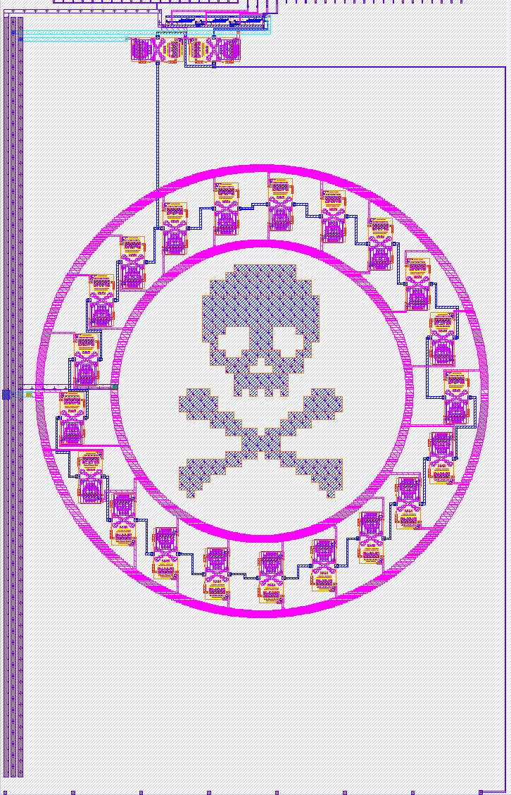
- Description: A stylish ring oscillator built from SkullFET transistors
- GitHub repository
- Open in 3D viewer
- Clock: 0 Hz
How it works
A simple yet stylish ring oscillator that uses a chain of 21 SkullFET inverters to generate a square wave output. Based on simulation, the oscillator should have a frequency of around 169.2 MHz.
| Pin | Expected frequency |
|---|---|
| osc_out | 169.2 MHz |
| osc_div_2 | 84.6 MHz |
| osc_div_4 | 42.3 MHz |
| osc_div_8 | 21.1 MHz |
| osc_out_3v3 | 169.2 MHz |
How to test
Connect an oscilloscope to one of osc_out_3v3 or osc_div_8 (uo_out pin 3) pin and enjoy the show. The remaining output pins, osc_out, osc_div_2, and osc_div_4, are likely to be changing too fast for GPIO pins to handle (the GPIO pins are limited to around 33 MHz), so you will probably not be able to observe them directly.
Simulation results
The following graph shows the output of the oscillator and the divided outputs. It was generated by running make -C sim and patiently waiting for the simulation to finish:
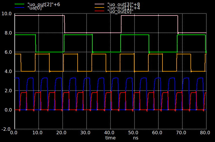
The outputs are shifted by 2 volts to make them easier to see in the graph. "uo_out[0]" is the main output of the oscillator, "ua[0]" is the 3v3 analog output, and "uo_out[1]"/"uo_out[2]"/"uo_out[3]" are the divided outputs.
Please note that the simulation results do not account for all parasitics, only the primary ones. Consequently, the actual frequency of the oscillator is likely to be lower than the simulated value.
IO
| # | Input | Output | Bidirectional |
|---|---|---|---|
| 0 | osc_out | ||
| 1 | osc_div_2 | ||
| 2 | osc_div_4 | ||
| 3 | osc_div_8 | ||
| 4 | |||
| 5 | |||
| 6 | |||
| 7 |
Analog pins
ua | PCB Pin | Internal index | Description |
|---|---|---|---|
| 0 | B2 | 8 | osc_out_3v3 |