162 Fuzzy Search Engine
162 : Fuzzy Search Engine
- Author: Peter Nørlund
- Description: A levenshtein based fuzzy search engine
- GitHub repository
- Open in 3D viewer
- Clock: 50000000 Hz
How it works
sky25a-levenshtein is a fuzzy search engine which can find the best matching word in a dictionary based on levenshtein distance.
Fundamentally its an implementation of the bit-vector levenshtein algorithm from Heikki Hyyrö's 2003 paper with the title A Bit-Vector Algorithm for Computing Levenshtein and Damerau Edit Distances.
Architecture
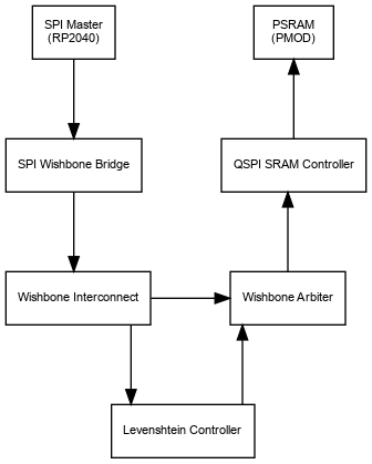
The overall architecture is a Wishbone Classic system with two masters (The levenshtein engine and an SPI controlled master) and two slaves (The levenshtein engine and a QSPI SRAM controller).
Using the SPI interface, you store a dictionary and some bitvectors representing a search word in SRAM and then configures and activates the engine. The engine will then read the dictionary and bitvectors from the SRAM and, ultimately store the index and distance of the word in the dictionary with the lowest levenshtein distance in registers which can be read by the user.
 {height=45%}
SPI
The device is organized as a wishbone bus which is accessed through commands on an SPI bus.
The maximum SPI frequency is 25% of the master clock (12.5MHz when the chip is running at 50MHz).
The bus uses SPI mode 3 (CPOL=1, CPHA=1)
Input bytes:
| Byte | Bit | Description |
|---|---|---|
| 0 | 7 | READ=0 WRITE=1 |
| 0 | 6-0 | Address bit 22-16 |
| 1 | 7-0 | Address bit 15-8 |
| 2 | 7-0 | Address bit 7-0 |
| 3 | 7-0 | Byte to write if WRITE, otherwise ignored |
Output bytes:
| Byte | Bit | Description |
|---|---|---|
| 0 | 7-0 | Byte read if READ, otherwise just 0x00 |
Since the SPI bridges to a wishbone bus which is shared by another master and because register and SRAM have different latencies, the response time is variable.
While the bus is working, the output bits will be zero. The final output byte will be preceeded by a one-bit.
Note that this means that the value 0x5A can appear 8 different ways on the SPI bus:
01 5A   0000000 1 01011010
02 B4   000000 1 01011010 0
05 68   00000 1 01011010 00
0A D0   0000 1 01011010 000
15 A0   000 1 01011010 0000
2B 40   00 1 01011010 00000
56 80   0 1 01011010 000000
AD 00   1 01011010 00000000
Memory Layout
The address space is 23 bits and is organized as follows:
| Address | Size | Access | Identifier |
|---|---|---|---|
| 0x000000 | 1 | R/W | CTRL |
| 0x000001 | 1 | R/W | SRAM_CTRL |
| 0x000002 | 1 | R/W | LENGTH |
| 0x000003 | 1 | R/O | MAX_LENGTH |
| 0x000004 | 2 | R/O | INDEX |
| 0x000006 | 1 | R/O | DISTANCE |
| 0x000200 | 512 | R/W | VECTORMAP |
| 0x000400 | 8M | R/W | DICT |
CTRL
The control register is used to start the engine and see when it has completed.
The layout is as follows:
| Bits | Size | Access | Description |
|---|---|---|---|
| 0 | 1 | R/W | Enable flag |
| 1-7 | 7 | R/O | Not used |
Set the enable flag to start the engine. When the engine is finished, the enable flag is changed to 0
SRAM_CTRL
Controls the SRAM
| Bits | Size | Access | Description |
|---|---|---|---|
| 0-1 | 2 | R/W | Chip select |
| 2-7 | 6 | R/O | Not used |
The chip select flag controls which chip select is used on the PMOD when accessing SRAM
| Value | Pin | Notes |
|---|---|---|
| 0 | None | Default value |
| 1 | CS | Uses the default CS on the PMOD (Pin 1). Compatible with Machdyne's QQSPI PSRAM |
| 2 | CS2 | Uses CS2 on the PMOD (pin 6). Compatible with mole99's QSPI Flash/(P)SRAM |
| 3 | CS3 | Uses CS3 on the PMOD (pin 7). Compatible with mole99's QSPI Flash/(P)SRAM |
LENGTH
| Bits | Size | Access | Description |
|---|---|---|---|
| 0-7 | 8 | R/W | Word length minus 1 |
Used to indicate the length of the search word. Note that the word cannot be empty and it cannot
exceed the maximum length as indicated by the MAX_LENGTH field.
MAX_LENGTH
| Bits | Size | Access | Description |
|---|---|---|---|
| 0-7 | 8 | R/O | Max word length supported minus 1 |
This field indicates the maximum supported length of the engine.
DISTANCE
When the engine has finished executing, this address contains the levenshtein distance of the best match.
INDEX
When the engine has finished executing, this address contains the index of the best word from the dictionary in big endian byte order.
VECTORMAP
The vector map must contain the corresponding bitvector for each input byte in the alphabet.
If the search word is application, the bit vectors will look as follows:
| Letter | Index | Bit vector |
|---|---|---|
a |
0x61 |
16'b00000000_01000001 (a_____a____) |
p |
0x70 |
16'b00000000_00000110 (_pp________) |
l |
0x6C |
16'b00000000_00001000 (___l_______) |
i |
0x69 |
16'b00000001_00010000 (____i___i__) |
c |
0x63 |
16'b00000000_00100000 (_____c_____) |
t |
0x74 |
16'b00000000_10000000 (_______t___) |
o |
0x6F |
16'b00000010_00000000 (_________o_) |
n |
0x6E |
16'b00000100_00000000 (__________n) |
| * | * | 16'b00000000_00000000 (___________) |
The size of the vectors is MAX_LENGTH bits rounded up to the nearest 8. The vectors are stored in big endian order.
The vector map is stored in SRAM so the values are indetermined at power up and must be cleared.
DICT
The word list.
The word list is stored of a sequence of words, each encoded as a sequence of 8-bit characters and terminated by the byte value 0x00. The list itself is terminated with the byte value 0x01.
Note that the algorithm doesn't care about the particular characters. It only cares if they are identical or not, so even though the algorithm doesn't support UTF-8 and is limited to a character set of 254 characters, ignoring Asian alphabets, a list of words usually don't contain more than 254 distinct characters, so you can practially just map lettters to a value between 2 and 255.
Levenshtein module
The levenshtein module is a state machine with 8 states:
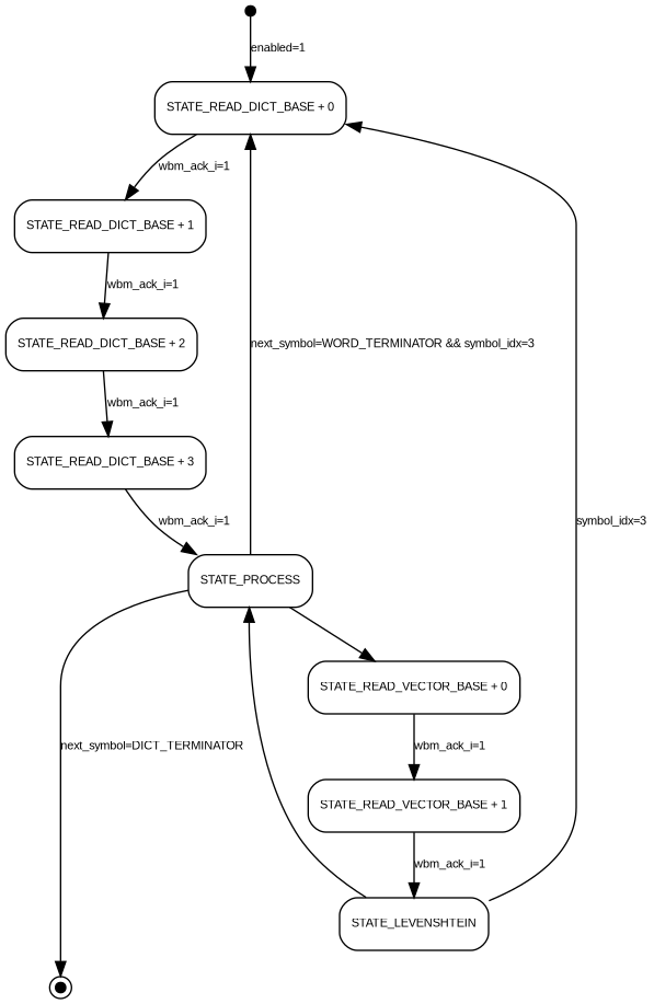
STATE_READ_DICT_BASE + n
At these states, four dictionary bytes are read from the PMOD PSRAM via the wishbone bus as indicated by dict_address.
The bytes are stored in a symbols buffer.
STATE_PROCESS
At this state each symbol in the symbols buffer is processed one byte per cycle. The symbol being processed is indicated by symbol_idx.
If the symbol processed is WORD_TERMINATOR (0x00) the best_idx and best_distance variables are updated and the bitvector engine is reset. If it was the last symbol, state changes to STATE_READ_DICT_BASE + 0.
If the symbol processed is DICT_TERMINATOR (0x01), the engine disables itself.
If the symbol is neigher WORD_TERMINATOR or DICT_TERMINATOR, the state changes to STATE_READ_VECTOR_BASE + 0.
STATE_READ_VECTOR_BASE + n
At these states a 16-bit vector is read from the PMOD SRAM in 8-bit chunks, representing the symbol being processed.
When both bytes has been read, state changes to STATE_LEVENSHTEIN
STATE_LEVENSHTEIN
At this state, the bitvector based levenshtein algorithm is run.
If it was the last symbol in the symbol buffer, state changes to STATE_READ_DICT_BASE + 0 - otherwise, state changes to STATE_PROCESS.
Summary
Unless the terminator symbols are reached, the states are:
STATE_READ_DICT_BASE + 0STATE_READ_DICT_BASE + 1STATE_READ_DICT_BASE + 2STATE_READ_DICT_BASE + 3STATE_PROCESS, symbol_idx=0STATE_READ_VECTOR_BASE + 0STATE_READ_VECTOR_BASE + 1STATE_LEVENSHTEINSTATE_PROCESS, symbol_idx=1STATE_READ_VECTOR_BASE + 0STATE_READ_VECTOR_BASE + 1STATE_LEVENSHTEINSTATE_PROCESS, symbol_idx=2STATE_READ_VECTOR_BASE + 0STATE_READ_VECTOR_BASE + 1STATE_LEVENSHTEINSTATE_PROCESS, symbol_idx=3STATE_READ_VECTOR_BASE + 0STATE_READ_VECTOR_BASE + 1STATE_LEVENSHTEINSTATE_READ_DICT_BASE + 0- ...
Reading from the PMOD PSRAM is done at half the frequency in 1S-4S-4S mode with 6 wait cycles, so going from STATE_READ_x_BASE + 0 to STATE_READ_x_BASE + 1 takes 44 cycles ((8 + 24/4 + 6 + 8/4) * 2 = 44) and the remaining states takes 4 cycles ((8 / 4) * 2 = 4). So processing 4 bytes of dictionary symbols takes 256 cycles (44 + 4 + 4 + 4 + (1 + 44 + 4 + 1) * 4 = 256) or 64 cycles/symbol.
Assuming a 512KiB dictionary and 50MHz clock, searching takes up to 671ms.
How to test
You can compile the client as follows:
mkdir -p build
cmake -G Ninja -B build .
cmake --build build
Next, you can run the test tool:
# Machdyne QQSPI PSRAM
./build/client/client --interface tt --test --verify-dictionary --verify-search

# mole99 PSRAM
./build/client/client --interface tt --cs cs2 --test --verify-dictionary --verify-search
This will load 1024 words of random length and characters into the SRAM and then perform a bunch of searches, verifying that the returned result is correct.
External hardware
To operate, the device needs a QSPI PSRAM PMOD. The design is tested with the QQSPI PSRAM PMOD from Machdyne, but any memory PMOD will work as long as it supports:
- WRITE QUAD with the command
0x38in 1S-4S-4S mode and no latency - FAST READ QUAD with the command
0xE8in 1S-4S-4S mode and 6 wait cycles - 24-bit addresses
- Uses pin 0, 6, or 7 for
SS#. - Must be able to run at half the clock speed of the TT chip.
Note that this makes it incompatible with the spi-ram-emu project for the RP2040.
IO
| # | Input | Output | Bidirectional |
|---|---|---|---|
| 0 | SRAM QSPI CS | ||
| 1 | SRAM QSPI SIO0/MOSI | ||
| 2 | SRAM QSPI SIO1/MISO | ||
| 3 | SRAM QSPI SCK | ||
| 4 | SPI SS# | SRAM QSPI SIO2 | |
| 5 | SPI SCK | SRAM QSPI SIO3 | |
| 6 | SPI MOSI | SRAM QSPI CS2 | |
| 7 | SPI MISO | SRAM QSPI CS3 |