841 AUTh DMA Controller
841 : AUTh DMA Controller

- Author: Spyridon Vasileiou, Zafeirios Giapoutzis, Athanasios Karatzas, Zisis Katsaros, Kiriakos Kokkinos
- Description: 8-bit DMA Controller for transferring data between memory and I/O device
- GitHub repository
- Open in 3D viewer
- Clock: 66000000 Hz
AUTh DMA Controller Documentation
Contents
- Overview
- I/O Configuration
- State Diagram
- How to test
Overview
The core function of the DMA Controller (DMAC) is to take over the system buses and transfer data from memory to an I/O device, or vice versa, when instructed by the CPU. In this implementation, the DMAC is synchronous with the CPU, while memory operates in a second clock domain and the I/O device operates in a third clock domain.
Both word and address width are 8 bits. The DMAC supports two operating modes:
- Single-word transfer mode
- Four-word burst mode
In burst mode, both source and destination addresses are incremented by 1 after each transfer. The DMAC is implemented as a finite state machine (FSM).
I/O Configuration
Since this project is submitted to a Tiny Tapeout shuttle, there is a strict pin budget: 8 input pins, 8 output pins, 8 bidirectional pins, and 2 pins for clock and reset.
The I/O pins are configured as follows.
Inputs
ui[7]:start- Sent by the CPU to indicate that transfer instructions are about to be provided.ui[6]:BG- Sent by the CPU to indicate that the DMAC is granted control of the system bus.ui[5]:rtrn- Sent by either memory or the I/O device to indicate either: (i) data sent by the DMAC has been received, or (ii) data loaded onto the transfer bus is ready to be read.ui[4:0]:cfg_in[4:0]- Configuration input from the CPU over 4 cycles, carrying mode, direction, source address, and destination address.
Outputs
uo[7]:BR- Sent to the CPU to request control of the system bus.uo[6]:WRITE_en- Sent to memory or the I/O device to indicate whether data should be written or read.uo[5]:done- Sent to the CPU when all transfers are complete.uo[4]:valid- Sent to memory or the I/O device to indicate that address/data on the transfer bus is valid.uo[3]:ack- Sent to memory or the I/O device to indicate that the DMAC has received incoming data.uo[2]:target- Indicates whether transfer bus address/data is intended for memory or the I/O device.uo[1:0]: Unused.
Bidirectional
uio[7:0]:transfer_bus[7:0]
How it works (+ State Diagram)
As mentioned before, our DMA Controller is structured as an FSM. In order to explain how it works, we will present each state individually. To further assist the reader's understanding, there is also a state diagram below the following list.
States
S0: IDLE- The DMAC stays in the
IDLEstate until the CPU pulls up thestartsignal.
- The DMAC stays in the
S1: PREPARATION- After the
startsignal is set to high, the FSM moves toPREPARATIONstate, where in the span of four cyclesmode,direction,src_addranddest_addrare fetched viacfg_in.
- After the
S2: WAIT4BG- Once the process above is done the
BRsignal is set to high and the FSM stays inWAIT4BGuntil the CPU grants access to the system bus viaBGinput signal.
- Once the process above is done the
S3: SRC_SEND- After
BGis set to high,SRC_SENDstate follows. In this statetransfer_busandtargetoutputs are configured so that they conveysrc_addrto either the Memory or the I/O Device (depending ondirection). After one cyclevalidis set to high and only then does the receiver fetch the address. This is done in order to mitigate metastability during CDC. After one more cycle the FSM moves toS4.
- After
S4: RECEIVE- In this state the FSM waits for a
rtrnsignal from the receiver. Shortly afterrtrnis set to high, artrn_risepulse is generated allowing the DMAC to fetch the data from thetransfer_bus. Additionally, anacksignal is sent back so that the device that sent the data knows that it was received. - It is important to mention that the source does not send an acknowledgement informing the DMAC that the
src_addrwas received. Rather, thertrnsignal functions both as an acknowledgement (for thesrc_addr) and as a fetch signal (for the data). This was done in order to fit the 8 pin input budget.
- In this state the FSM waits for a
S5: SENDaddr- After
rtrn_risepulses the FSM moves toSENDaddrstate where the DMAC sends thedst_addrto the destination. The address and the target are loaded to thetransfer_busandtargetoutputs and after one cyclevalidis set to high. The DMAC now waits for artrn_risepulse similar to theRECEIVEstate.
- After
S6: SENDdata- In
SENDdatathe DMAC sends data to the destination and the process is identical toSENDaddr. Afterrtrn_risepulses, the FSM moves toS3if there are more words left to transfer; otherwise, it moves toS0. In the latter caseBRis set to low anddoneis set to high, indicating that the transfer has been successfully completed.
- In
- EXTRA: Timeout logic
- This is not a state, but rather a check happening in every state where a
rtrn_risepulse is required to move to a subsequent state (S4,S5,S6). By setting the localparamtimeout_limitinproject.vto the desired number of clock cycles the FSM will move toS0if nortrn_risepulse is generated in the span oftimeout_limitclock cycles after the FSM has entered eitherS4,S5orS6. In such case bothBRanddoneare set to low indicating that the transfer has failed.
- This is not a state, but rather a check happening in every state where a
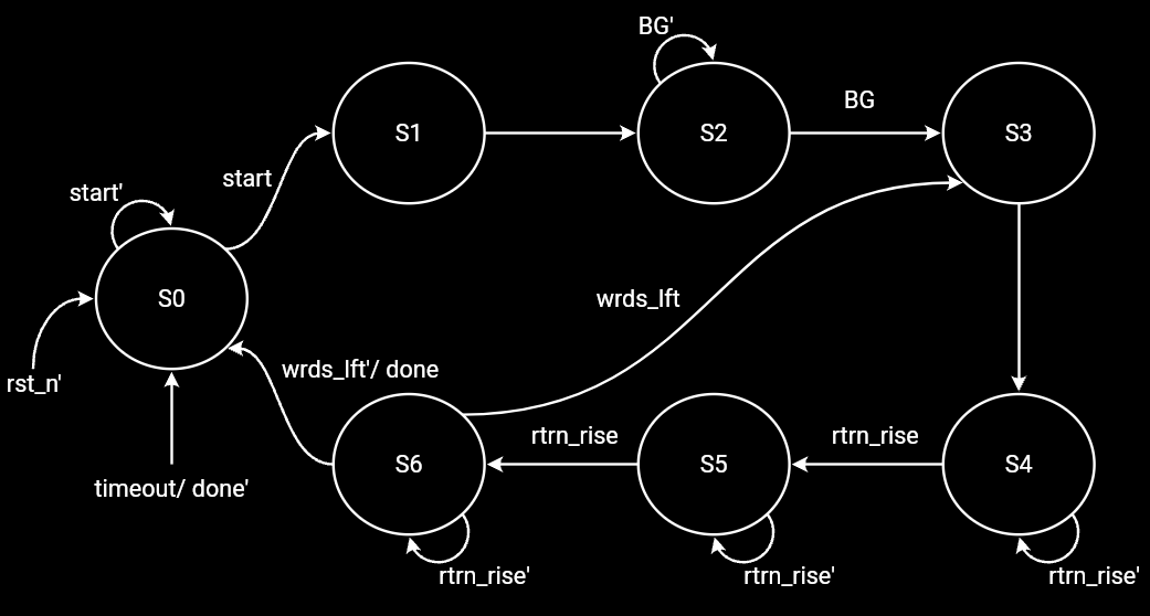
Notes:
rtrn_riseis an internal pulse generated shortly afterrtrnrises to high.- Similarly,
timeoutis an internal signal indicating thatrtrn_risehas not been generated in time wrds_lftis not an actual signal; it indicates whether there are still words left to transfer in four-word burst mode.
How to test
This project uses a cocotb-based Python testbench and runs simulation with Icarus Verilog.
The entry point for this flow is test/run_cocotb.py.
1. Requirements
You need all of the following:
- Python 3.10+ (tested in this repo with Python 3.13)
pip(Python package installer)- Icarus Verilog (
iverilogandvvpavailable in PATH) - The Python packages in
test/requirements.txt:pytest==8.4.2cocotb==2.0.1
Optional:
- GTKWave for waveform viewing (
.fstfiles)
2. Install system dependencies
Install Icarus Verilog first.
Windows (PowerShell, winget):
winget install IcarusVerilog.IcarusVerilog
Linux (Debian/Ubuntu):
sudo apt update
sudo apt install -y iverilog
macOS (Homebrew):
brew install icarus-verilog
Note for macOS: If unable to open, right-click on the app and select Open.
Optional GTKWave:
- Windows:
winget install gtkwave.gtkwave - Linux:
sudo apt install -y gtkwave - macOS:
brew install --cask gtkwave
3. Create and activate a Python virtual environment
From repository root:
Windows (PowerShell):
python -m venv .venv
.\.venv\Scripts\Activate.ps1
Linux/macOS:
python3 -m venv .venv
source .venv/bin/activate
If PowerShell blocks activation scripts, allow local scripts in your current user scope:
Set-ExecutionPolicy -ExecutionPolicy RemoteSigned -Scope CurrentUser
4. Install Python test dependencies
From repository root with .venv activated:
python -m pip install --upgrade pip
python -m pip install -r test/requirements.txt
If you see an import error for cocotb_tools, reinstall cocotb and the test requirements:
python -m pip install -r test/requirements.txt
Special Case: Python 3.14+ (macOS Compatibility): If you are using Python 3.14 or newer, cocotb might block installation due to version checks. Use this workaround:
export COCOTB_IGNORE_PYTHON_REQUIRES=1 pip install cocotb cocotb-bus pytest
5. Verify tools are available
iverilog -V
vvp -V
python -c "import cocotb; print(cocotb.__version__)"
Expected:
- Icarus version information prints
- cocotb version prints (should be
2.0.1)
6. Run the cocotb flow (run_cocotb.py)
From repository root:
python test/run_cocotb.py
Note for macOS:
If run_cocotb.py fails with ModuleNotFoundError: No module named 'cocotb_tools', ensure your script uses from cocotb.runner import get_runner (updated syntax).
What this script does:
- Builds the testbench with Icarus using:
- DUT:
src/project.v - testbench wrapper:
test/tb.v
- DUT:
- Runs cocotb tests from
test/test.py. - Generates simulation artifacts under
test/sim_build/rtl/. - Auto-generates
cocotb_iverilog_dump.vinsidetest/sim_build/rtl/as part of cocotb/iverilog waveform setup.
7. Expected passing result
You should see a cocotb summary similar to:
TESTS=4 PASS=4 FAIL=0 SKIP=0
The current suite runs these tests:
test_single_word_modetest_burst4_modetest_randomized_clock_and_transfer_stresstest_all_speed_profile_combinations
8. Output files to know
Important outputs after a run:
- Build artifacts:
test/sim_build/rtl/ - Main waveform:
test/sim_build/rtl/tb.fst - Auto-generated dump helper:
test/sim_build/rtl/cocotb_iverilog_dump.v - cocotb XML report:
test/results.xml
9. Optional waveform viewing
After a successful run, a waveform file is generated at test/sim_build/rtl/tb.fst (or .vcd).
If GTKWave is installed:
gtkwave test/sim_build/rtl/tb.fst test/tb.gtkw
Otherwise you can use Surfer, an online waveform viewer. Surfer can also be installed as a VS Code extension. You can load a saved state via \test\state_preset file, which includes all important signals.
10. Troubleshooting
iverilognot found:- Install Icarus Verilog and reopen terminal so PATH refreshes.
ModuleNotFoundError: cocotb:- Activate
.venvand reinstall-r test/requirements.txt.
- Activate
ModuleNotFoundError: cocotb_tools:- Run
python -m pip install -r test/requirements.txt. - If needed, install cocotb directly with
python -m pip install cocotb.
- Run
- Tests time out or fail unexpectedly:
- Ensure you are running the repository's intended branch and rerun with a clean
test/sim_builddirectory.
- Ensure you are running the repository's intended branch and rerun with a clean
- Zsh parse error:
- Ensure you are not pasting multi-line comments directly into the terminal without proper escaping.
IO
| # | Input | Output | Bidirectional |
|---|---|---|---|
| 0 | cfg_in[0] | transfer_bus[0] | |
| 1 | cfg_in[1] | transfer_bus[1] | |
| 2 | cfg_in[2] | target | transfer_bus[2] |
| 3 | cfg_in[3] | ack | transfer_bus[3] |
| 4 | cfg_in[4] | valid | transfer_bus[4] |
| 5 | rtrn | done | transfer_bus[5] |
| 6 | BG | WRITE_en | transfer_bus[6] |
| 7 | start | BR | transfer_bus[7] |