331 DDS Waveform Generator - IEEE
331 : DDS Waveform Generator - IEEE

- Author: Daniel Roberto Garcia Miranda
- Description: Programmable DDS waveform generator with multiple waveforms, frequency and amplitude control
- GitHub repository
- Open in 3D viewer
- Clock: 50000000 Hz
How it works
This project implements a Direct Digital Synthesis (DDS) waveform generator.
The core of the design is a Phase Accumulator that increases every clock cycle by a programmable frequency control word (freq_word). The output frequency follows the standard DDS formula:
$f_{out} \approx \frac{freq_word}{2^{16}} \cdot f_{clk}$
The most significant bits (MSB) of the accumulator are used to generate five different waveforms:
- Sine: Generated via a 16-entry Lookup Table (LUT).
- Sawtooth: Derived directly from the phase value.
- Square: Generated by checking the MSB of the phase (50% duty cycle).
- Triangle: Created by bit-manipulation of the phase (inverted ramp).
- Quadratic: A parabolic curve generated by squaring the phase value.
The design is optimized for a 50 MHz system clock and provides an 8-bit digital output.
Control Table (ui_in[7:0])
The 8-bit input controls the generator's behavior:
| Bits | Function |
|---|---|
| [7:6] | Frequency Control |
| [5:3] | Amplitude Control |
| [2:0] | Waveform Selection |
Waveform Selection (ui_in[2:0])
| Bits | Function |
|---|---|
| 000 | Sine |
| 001 | Sawtooth |
| 010 | Square |
| 011 | Triangle |
| 100 | Quadratic |
Frequency Control (ui_in[7:6])
| Bits | freq_word (Dec) | Description |
|---|---|---|
| 00 | 128 | Low frequency |
| 01 | 512 | Medium-low |
| 10 | 1024 | Medium-high |
| 11 | 4096 | High frequency |
Amplitude Control (ui_in[5:3])
| Bits | Level | Scaling Factor |
|---|---|---|
| 000 | Low | 12.5% |
| 001 | Medium-Low | 25% |
| 010 | Medium-High | 50% |
| 111 | Maximum | 100% |
How to test
- Apply a 50 MHz clock to
clkand release reset (rst_n = 1). - Set
ui_into select your desired output (e.g.,8'b00_111_000for a 100% Amplitude Sine Wave at low frequency). - Observe the 8-bit output
uo_out.
Simulation in Vivado
- Run the behavioral simulation using the provided
test/tb.v. - To view the signals exactly as shown in the documentation, open the pre-configured waveform file:
test/waveforms/main_waveform_config.wcfg
Simulation Results
The image below demonstrates the transitions between different waveforms and the impact of amplitude scaling.
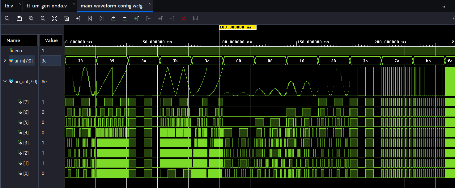
Note: The uo_out signal is displayed in 'Analog' style with 'Hold' interpolation for better visualization.
External Hardware
To visualize the generated waveforms on an oscilloscope, an external Digital-to-Analog Converter (DAC) is required.
Recommended DAC Characteristics
- Resolution: 8-bit (to match
uo_out). - Input: Parallel digital input.
- Voltage Range: 0V to 3.3V.
- Sample Rate: Supports up to 50 MHz.
Implementation Options
1. R-2R Resistor Ladder (Recommended)
Building an R-2R ladder is the most direct way to convert the 8-bit parallel data.
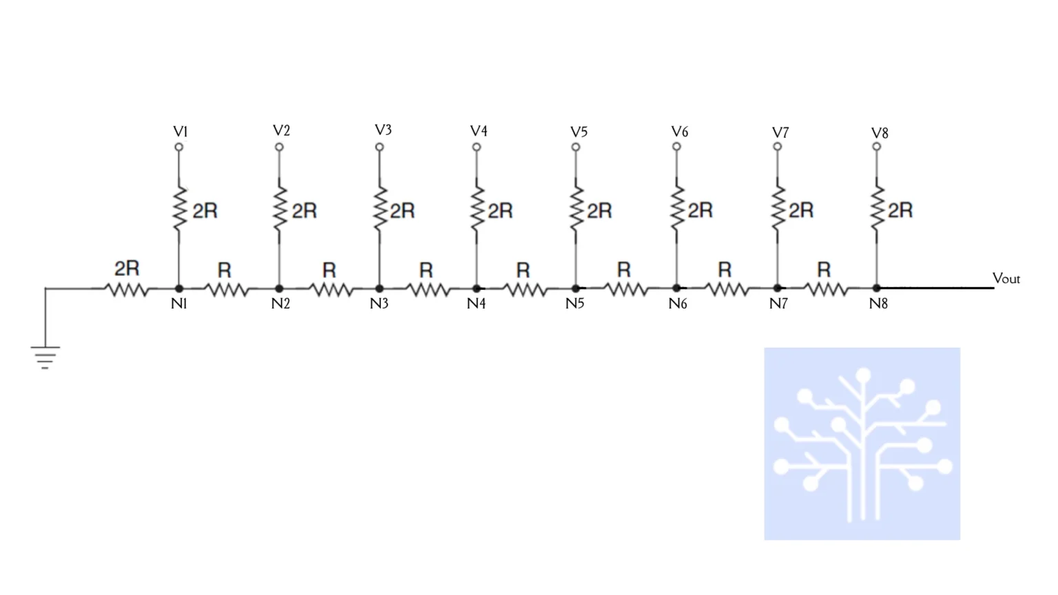
Pro Tip: Use 1% precision resistors to ensure the linearity of the analog steps and avoid "ghosting" or distortion in the signal.
2. Dedicated DAC IC
For higher signal integrity, use a parallel-input DAC like the DAC0808. If using a serial DAC (SPI/I2C), external shift registers will be necessary to convert the parallel output.
IO
| # | Input | Output | Bidirectional |
|---|---|---|---|
| 0 | func_sel[0] | out[0] | |
| 1 | func_sel[1] | out[1] | |
| 2 | func_sel[2] | out[2] | |
| 3 | amp_ctrl[0] | out[3] | |
| 4 | amp_ctrl[1] | out[4] | |
| 5 | amp_ctrl[2] | out[5] | |
| 6 | freq_ctrl[0] | out[6] | |
| 7 | freq_ctrl[1] | out[7] |