482 Tiny_Tapeout_Launch_Controller
482 : Tiny_Tapeout_Launch_Controller

- Author: Eric Pearson
- Description: Launch control chip
- GitHub repository
- Open in 3D viewer
- Clock: 48000000 Hz
How it works
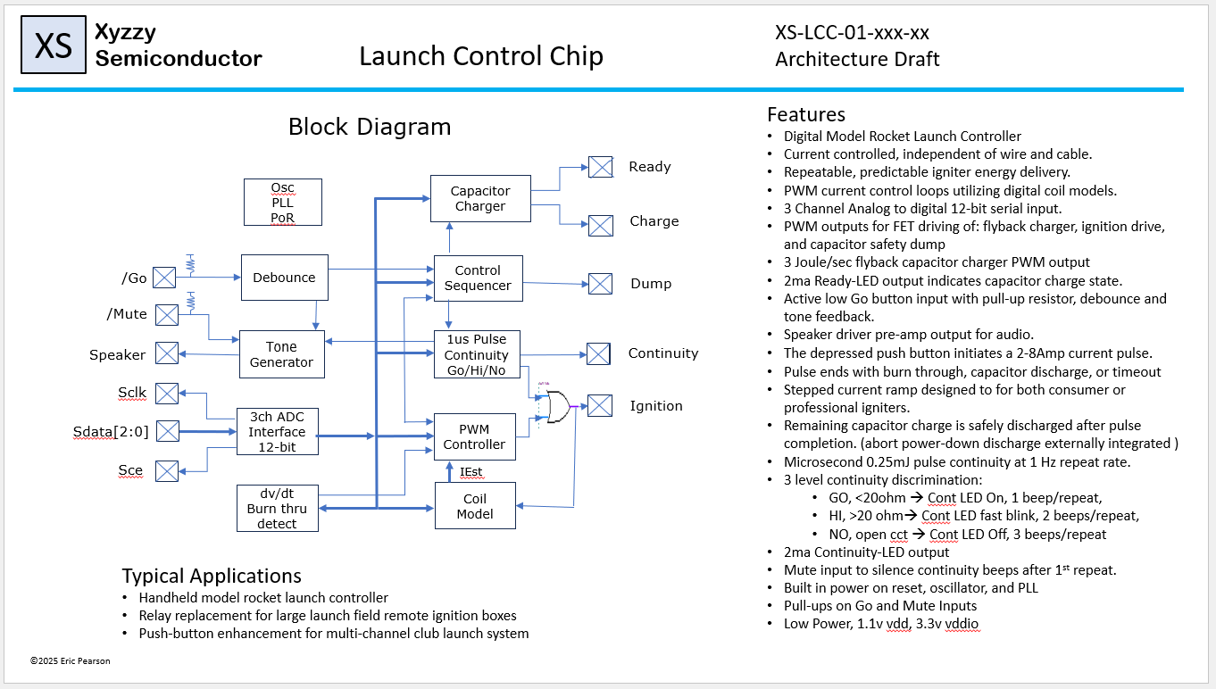
This chip is the core for a complete system for a capacitive discharge model rocket launch controllers. It provides capacitor charging, igniter continuity testing, current controlled igniter drive, and safety capacitor energy dump. It provides a control and status interface suitable for either digital or direct front panel and speaker connections. The chip implements complete system control from power on, charging, continuity, launch, and dump of capacitor energy. The algorithms control the systems power stage via digital pwm outputs based on ADC serial input feedback. There are 3 pwm outputs to control: 1amp capacitor charger, a 2- 8amp igniter output, and a 25watt resistor capacitor energy dump. The capacitor charger generates a pwm output for a flybackconverter with optimized for 1amp battery operation and while charging to 320V. The ignition driver generates a pwm output for a buck-converter that delivers constant current control over the full capacitor discharge voltage range. The igniter current pulse profile begins with steps from 2 amps to 8 amps suitable for 0.5ohm consumer and 2ohm profession igniters and matches. The full energy of the capacitor is used with a timeout and burn-through detection for robustness. The energy dump drives an external discharge circuit to dump any remaining capacitor charge into a load power resistor upon completion.
How to test
The device has BIST.
BIST is started by asserting ui_in[7] = 0 at reset (just set all ui_in = 0 ). An integer system simulation model and model of the ADC serial interface are employed. During the 65ms after reset a truncated full system simulation is performed. During this time the uo_out counts from 0 to a passing value of uo_out==8'hC0. It will stop at lower values if any test asserts are violated.
So test operation is:
clk on
ui_in = 8'h00
reset deasserted
wait >65ms (65*48000 cycles)
read uo_out
pass 8'hc0
External hardware
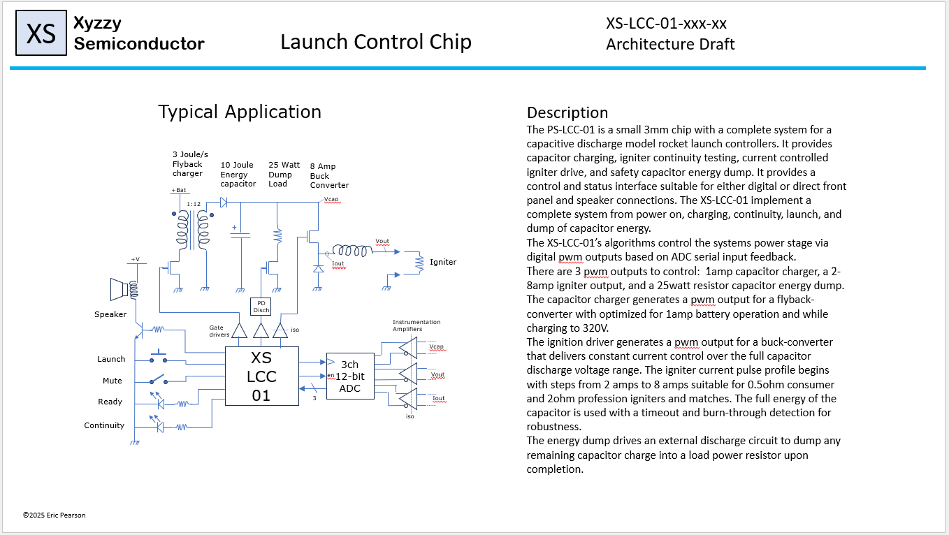
List external hardware used: - 3 channels of 12 bit ADC simultaneous sampleing at 3Mhz - PWM controlled flyback transformer with FET and driver to charge a capacitor - PWM controlled output FET with flaoting driver and output inductdor - PWM controlled dump FET with driver and dump resistor. - speaker with transistor driver - Launch and mute button inputs to GND, with pullup resistors - Arm and continuity LEDs active high outputs. - and of course an output load in the range of 0 to 100 ohms (typ 0.5 to 2 ohm)
IO
| # | Input | Output | Bidirectional |
|---|---|---|---|
| 0 | Launch_n | Arm_led | |
| 1 | Mute_n | Cont_led | |
| 2 | Adc_Iout | Speaker | |
| 3 | Adc_Vout | Charge | |
| 4 | Adc_Vcap | Drive | |
| 5 | Dumpm | ||
| 6 | Adc_cs | ||
| 7 | Test_n |