516 HSXO
516 : HSXO
- Author: htfab
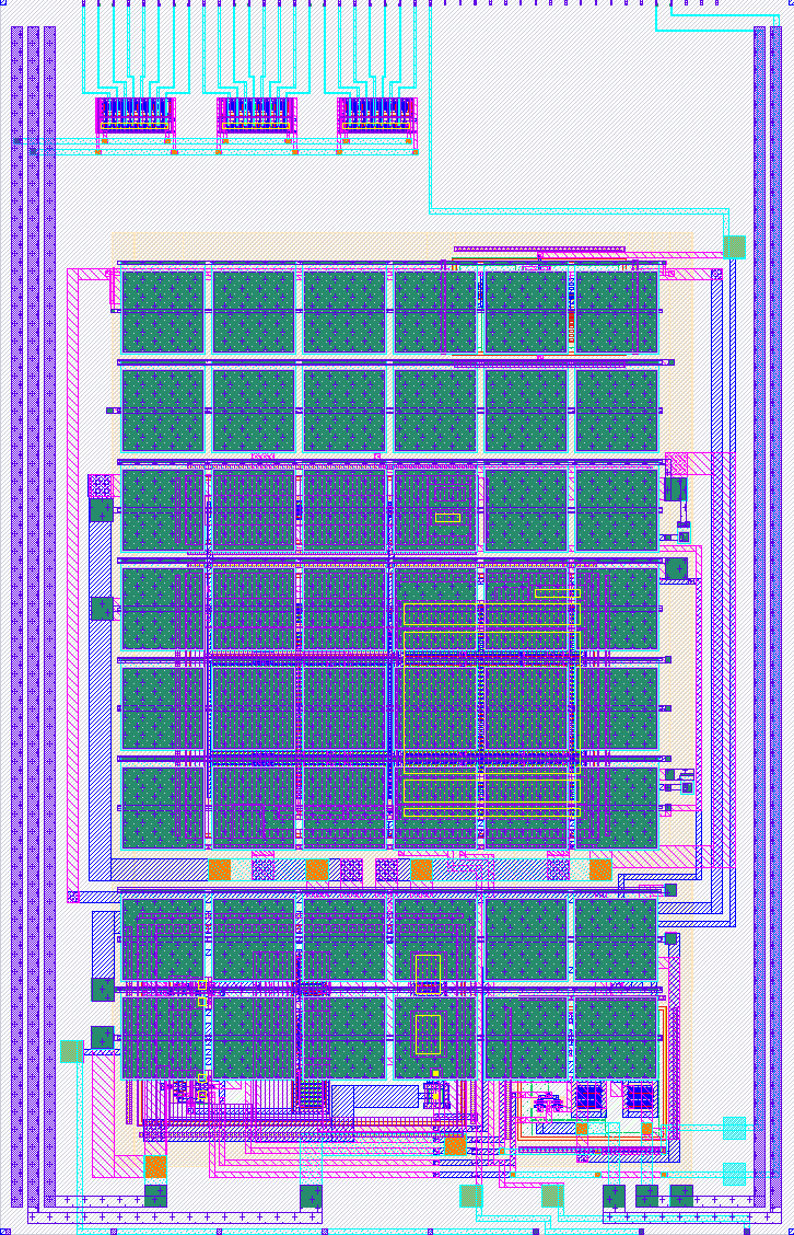
- Description: High-speed crystal oscillator IP block from Chipalooza 2024 wrapped into the TT analog template
- GitHub repository
- Open in 3D viewer
- Clock: 0 Hz
How it works
Wraps the high-speed crystal oscillator (HSXO) IP block from Chipalooza 2024 into a Tiny Tapeout project.
How to test
Build the Pierce oscillator circuit:
- Bridge XIN and XOUT with a passive crystal*.
- Add load capacitors** from XIN to ground and from XOUT to ground.
Supply a bias current of 1uA into the IBIAS pin.
Set the digital input ENA high and STDBY low.
You should see a clock signal on the digital pin DOUT after a short start-up delay.
You can monitor the start-up progress or the oscillation waveform by directly probing XIN and XOUT, but be mindful of the effect of your probe on the circuit.
* The IP block could theoretically support crystals between 4 and 16 MHz, but the higher end of the range would need shorter traces than those on the TT demoboard.
** C1 = C2 = 2 * (CL - Cstray) where CL comes from the crystal datasheet and Cstray is the stray capacitance of the pins and traces. A typical crystal in the supported range would have a CL around 12-20 pF, so accounting for 2-5 pF of stray capacitance I would start with a pair of 22 pF capacitors first. If the circuit doesn't start up, decrease the capacitors.
External hardware
Passive crystal, capacitors, bias current generator
IO
| # | Input | Output | Bidirectional |
|---|---|---|---|
| 0 | ENA | DOUT | |
| 1 | STDBY | ||
| 2 | |||
| 3 | |||
| 4 | |||
| 5 | |||
| 6 | |||
| 7 |
Analog pins
ua | PCB Pin | Internal index | Description |
|---|---|---|---|
| 0 | B1 | 7 | XOUT |
| 1 | B3 | 9 | XIN |
| 2 | B2 | 8 | IBIAS |