545 DNA_Accel
545 : DNA_Accel
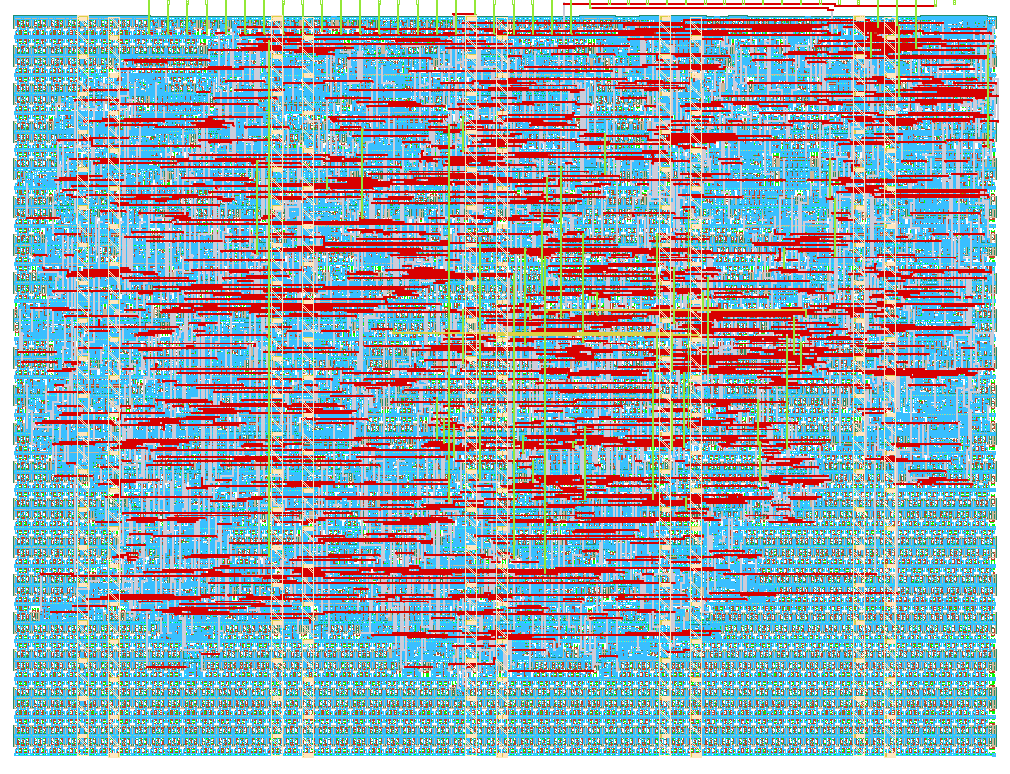
- Author: Garv R Jain, Suhani Das, Dr. Vishal Gupta
- Description: SPI-driven hardware accelerator for transition/transversion-aware DNA sequence comparison
- GitHub repository
- Open in 3D viewer
- Open in Tiny Tapeout Explorer
- Clock: 50000000 Hz
How it works
DNA_Accel is a hardware-accelerated DNA sequence comparator, controlled entirely over SPI. The host loads an 8-base pattern and an 8-base DNA window (2 bits per base, packed into 16-bit registers), and the chip scores their similarity in hardware: each of the 8 base positions is compared in parallel and classified as an exact match, a transition (the biologically "softer" mismatch, A<->G or C<->T), or a transversion (any other mismatch). Exact matches score 2 points, transitions score 1, transversions score 0, giving a total similarity of 0-16.
Because a single similarity number is ambiguous (e.g. 14 could mean 7 exact + 1 transversion, or 6 exact + 2 transitions), the design also computes unambiguous hardware counts of exact/transition/transversion bases (each 0-8, always summing to 8), plus a per-base mismatch mask and a packed vector of raw 2-bit scores, so the host can tell exactly which bases differ and how.
Internally the design is layered: spi_lite is a generic byte-level SPI slave with no protocol awareness;
bioaccel_spi_decoder implements the BioAccel command/register protocol (write/read/stream, register
addressing); dna_accelerator_top is pure comparison logic (registers -> comparator -> similarity/mutation
scoring) with no SPI awareness at all. The whole design runs on a single clock: the host's own SPI clock
(SCK), wired to the chip's dedicated clk pin -- there is no separate on-chip system clock.
How to test
Drive the SPI clock (SCK) on the dedicated clk pin, and control cs_n and mosi on ui[0] and ui[1];
read miso back on uo[0]. All communication uses SPI mode 0 (idle low, data driven on the falling edge,
sampled on the rising edge), MSB first.
Write (3 bytes): 0x01 (CMD_WRITE), address, data
Read (4 bytes): 0x02 (CMD_READ), address, 0x00 (spacer), then the response byte is clocked out on
miso during this 4th byte.
Register map:
| Addr | Register | Access |
|---|---|---|
| 0x00 | Pattern low byte | Write |
| 0x01 | Pattern high byte (latches load) | Write |
| 0x02 | DNA low byte | Write |
| 0x03 | DNA high byte (latches load) | Write |
| 0x04 | Similarity score (0-16) | Read |
| 0x05 | Match flag (1 = perfect score) | Read |
| 0x06 | Position, low byte | Read |
| 0x07 | Position, high byte | Read |
| 0x08 | Mismatch vector, low byte | Read |
| 0x09 | Mismatch vector, high byte | Read |
| 0x0A | Mismatch mask (1 bit/base) | Read |
| 0x0B | Exact-match count (0-8) | Read |
| 0x0C | Transition count (0-8) | Read |
| 0x0D | Transversion count (0-8) | Read |
To sanity-check the design: write the pattern and DNA registers with identical 16-bit values (e.g. both
0x0000), then read address 0x04 -- similarity should read back 16 and address 0x05 should read 1
(perfect match). Change a few bits in the DNA registers and re-read; similarity should drop, the mismatch
mask (0x0A) should show which bases changed, and the exact/transition/transversion counts (0x0B-0x0D)
should always sum to 8.
External hardware
None -- the design only needs a host capable of driving an SPI-like clock/data/chip-select interface (e.g. a Raspberry Pi, ESP32, Arduino, or PC-based SPI adapter). No PMODs, displays, or other peripherals are required.
IO
| # | Input | Output | Bidirectional |
|---|---|---|---|
| 0 | cs_n (active-low SPI chip select) | miso (SPI data out) | |
| 1 | mosi (SPI data in) | ||
| 2 | |||
| 3 | |||
| 4 | |||
| 5 | |||
| 6 | |||
| 7 |