552 TinyAnalogExperiments
552 : TinyAnalogExperiments
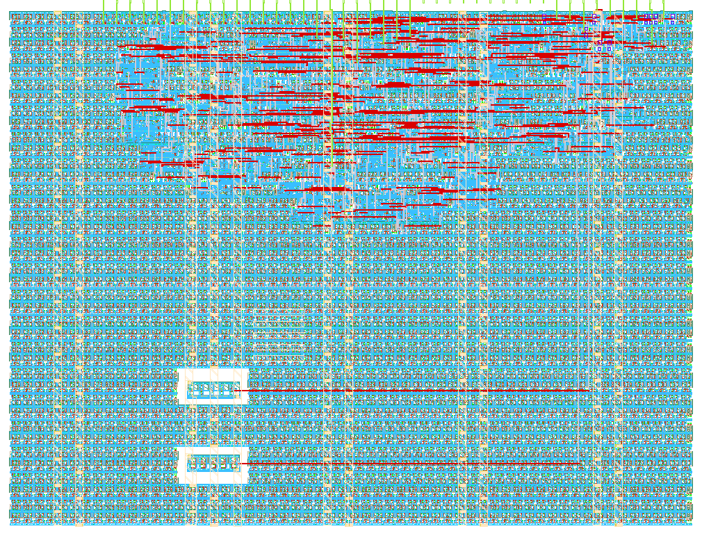
- Author: Hackin7
- Description: Dual ring oscillators (100/500 MHz) and 64-bit counter
- GitHub repository
- Open in 3D viewer
- Open in Tiny Tapeout Explorer
- Clock: 50000000 Hz
How it works
Hierarchical Tiny Tapeout top with analog ring leaves and a digital counter:
- 100 MHz transistor ring (
ring_oscillatorGDS macro). - 500 MHz transistor ring (
ring_oscillator_500mhzGDS macro). - 64-bit digital counter (
digital_counterRTL).ui_in[0]enables counting,ui_in[4:2]selects which counter byte drivesuo_out.
Clock select (change only while rst_n is low):
ui_in[1] |
ui_in[5] |
Counter clock |
|---|---|---|
| 0 | x | Tiny Tapeout clk |
| 1 | 0 | 100 MHz ring |
| 1 | 1 | 500 MHz ring |
Ring-clock modes are not timing qualified.
How to add more analog or digital leaves: see docs/hierarchy.md.
How to test
Hold reset, set ui_in[1] / ui_in[5] for the clock source, release reset,
set ui_in[0] to enable the counter, and read uo_out while sweeping
ui_in[4:2].
External hardware
None beyond the Tiny Tapeout board clock and GPIO.
IO
| # | Input | Output | Bidirectional |
|---|---|---|---|
| 0 | counter_enable | counter_byte[0] | |
| 1 | clock_select_ring | counter_byte[1] | |
| 2 | counter_byte_select[0] | counter_byte[2] | |
| 3 | counter_byte_select[1] | counter_byte[3] | |
| 4 | counter_byte_select[2] | counter_byte[4] | |
| 5 | clock_select_500mhz | counter_byte[5] | |
| 6 | counter_byte[6] | ||
| 7 | counter_byte[7] |