352 Mixer
352 : Mixer
- Author: Niklaus Leuenberger
- Description: Mixed-signal experimentation
- GitHub repository
- Open in 3D viewer
- Open in Tiny Tapeout Explorer
- Clock: 0 Hz
How it works
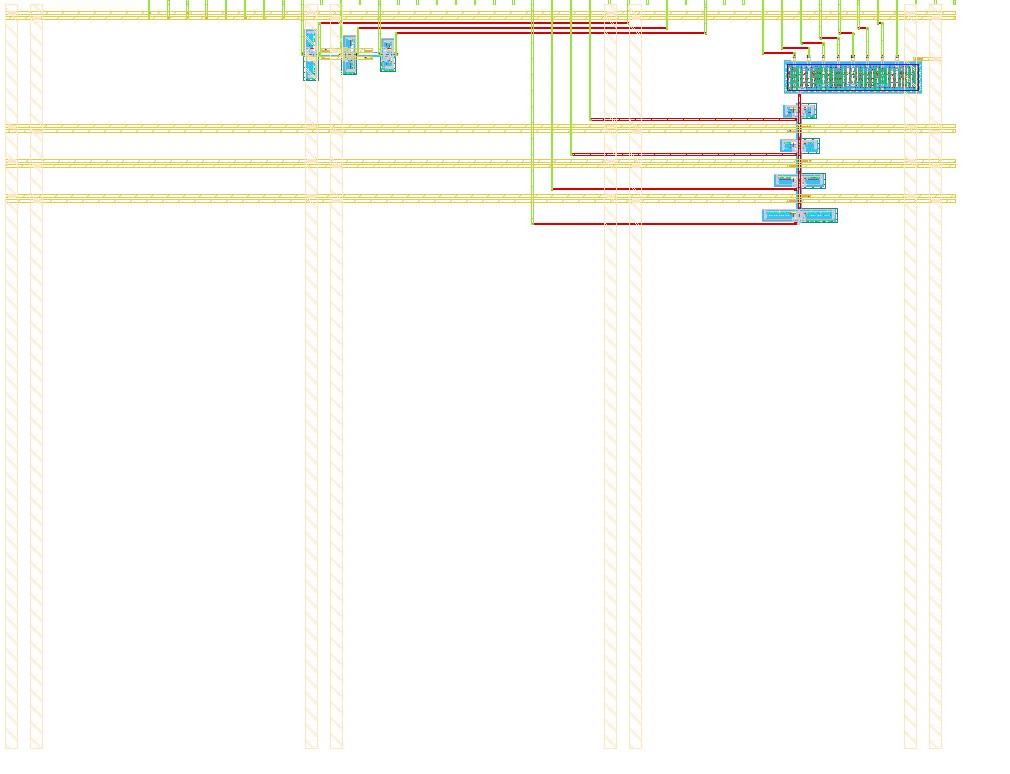
Various inverting schmitt triggers with different thresholds are attached to an internal DAC. The voltage produced by the DAC can be controlled with the digital inputs ui_in[7:0]. Each schmitt trigger then presents its state on the corresponding uo_out[7:0] pin.
Additional free standing inverting schmitt triggers are available on the bidirectional pins. With these and external RC components simple oscillators can be built.
How it came to be
Thanks to swiss chips sponsoring I was able to participate in the previous IHP26a run with a 8-bit floating point multiplier. There I took everything the OSS tools offer to us to squeeze a near perfect design out of very imperfect and lazy HDL code. Great.
But now for this second IHP16b TT run I needed to go a level deeper: To the physical world. No nice zeros and ones but only the raw analoginess of CMOS technology.
The initial idea was to again build a multiplier. But it would multiply in the physical world! I.e. produce some voltages that by nature get multiplied together and then converted back to digital. Easy! No not so much. Just the amount of stuff necessary to make that last bit, the ADC work, is too much. Sure, others made some. But I'm chronically late and the design is due in a month.
So what else can we do? Analog tiles are not available for this run. But nothing prohibits us from using analog stuff inside a digital facade. So we have a digitally controlled voltage, well a DAC, which then feeds into multiple schmitt triggers each with different threshold. That way we can sort of gauge the voltage that was produced internally.
How to test
TBD
External hardware
TBD
IO
| # | Input | Output | Bidirectional |
|---|---|---|---|
| 0 | DAC[0] | trigger1v1 | |
| 1 | DAC[1] | trigger2v1 | |
| 2 | DAC[2] | trigger4v1 | ST1v1_IN |
| 3 | DAC[3] | trigger8v1 | ST1v1_OUT |
| 4 | DAC[4] | ST2v1_IN | |
| 5 | DAC[5] | ST2v1_OUT | |
| 6 | DAC[6] | ST4v1_IN | |
| 7 | DAC[7] | ST4v1_OUT |