609 TinySoC
609 : TinySoC
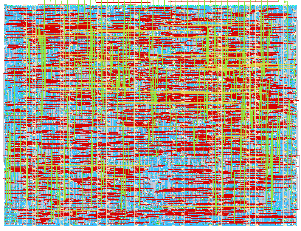
- Author: Maadesh
- Description: An 8-bit Harvard Architecture microcontroller with UART, GPIO, and PWM
- GitHub repository
- Open in 3D viewer
- Open in Tiny Tapeout Explorer
- Clock: 50000000 Hz
TinySoC Datasheet
Overview
TinySoC is a highly optimized, 8-bit Harvard Architecture microcontroller designed to fit securely inside a 1x1 Tiny Tapeout tile (IHP SG13G2 130nm). It executes instructions out of an external ROM or memory emulator connected to the input pins, while handling internal data through its onboard 8-byte RAM and memory-mapped peripheral registers.
Despite its microscopic footprint, the core features a fully functional 3-stage pipeline (Fetch, Fetch Operand, Execute) ensuring stable timing at 50 MHz, and a rich 17-instruction ISA supporting conditional branching, arithmetic flags, and hardware subroutines (CALL/RET).
Architecture Block Diagram
- CPU Core: 8-bit accumulator-based state machine.
- Instruction Memory: External via
ui[7:0]. - Data Memory: 8 Bytes Internal RAM.
- Peripherals: Memory-mapped UART, PWM, Timer, GPIO.
Pinout Mapping
ui[7:0]- Instruction Bus (Input from external ROM)uo[7:0]- Program Counter (Output to ROM address lines)uio[4:0]- GPIO Array (Bidirectional)uio[5]- UART TX (Transmit output)uio[6]- UART RX (Receive input)uio[7]- PWM OUT (Pulse Width Modulation output)
Memory Map
Memory space is divided between Internal RAM and Peripherals.
| Address | Description | Type |
|---|---|---|
0x00 - 0x07 |
Internal Scratchpad RAM (8 Bytes) | R/W |
0x20 |
GPIO Data (Read gets Input, Write sets Output) | R/W |
0x21 |
GPIO Direction Register (1 = Output, 0 = Input) | R/W |
0x22 |
Hardware Timer (Read: Current value, Write: Reset to 0) | R/W |
0x23 |
UART RX Data (Read gets data, automatically clears ready flag) | R |
0x24 |
UART TX Data (Writing initiates transmission) | W |
0x25 |
UART Status (Bit 0: RX Ready, Bit 1: TX Busy) | R |
0x26 |
PWM Duty Cycle | R/W |
0x28 |
UART Baud Divider Low Byte (BAUD_DIV_L) |
R/W |
0x29 |
UART Baud Divider High Byte (BAUD_DIV_H) |
R/W |
Instruction Set Architecture (ISA)
All instructions are fixed 16-bit words (Opcode + Operand).
| Opcode | Mnemonic | Description | Flags Affected |
|---|---|---|---|
0x01 |
LDI val |
Load Immediate val into Accumulator (ACC) |
Z |
0x02 |
LDR addr |
Load ACC from Memory Address addr |
Z |
0x03 |
STR addr |
Store ACC to Memory Address addr |
None |
0x04 |
ADD addr |
Add memory at addr to ACC |
Z, C |
0x05 |
SUB addr |
Subtract memory at addr from ACC |
Z, C |
0x06 |
JMP addr |
Jump unconditionally to addr |
None |
0x07 |
JZ addr |
Jump to addr if Zero Flag (Z) is 1 |
None |
0x08 |
AND addr |
Bitwise AND memory at addr with ACC |
Z |
0x09 |
OR addr |
Bitwise OR memory at addr with ACC |
Z |
0x0A |
XOR addr |
Bitwise XOR memory at addr with ACC |
Z |
0x0B |
SHL addr |
Logical Shift Left ACC by memory at addr |
Z |
0x0C |
SHR addr |
Logical Shift Right ACC by memory at addr |
Z |
0x0D |
CALL addr |
Push return address and Jump to addr |
None |
0x0E |
RET |
Return from subroutine | None |
0x0F |
JNZ addr |
Jump to addr if Zero Flag (Z) is 0 |
None |
0x10 |
JC addr |
Jump to addr if Carry Flag (C) is 1 |
None |
0xFF |
NOP |
No Operation (Any unmapped opcode is a NOP) | None |
Peripheral Usage Guides
UART (Dynamic Baud Rate)
The UART features a dynamic 16-bit baud rate divider mapped to 0x28 and 0x29.
The required divider value is Clock_Frequency / Target_Baud_Rate.
It defaults to 434 on reset, which provides 115200 baud at 50 MHz.
- Transmit: Poll
0x25until Bit 1 is0(not busy). Write data to0x24. - Receive: Poll
0x25until Bit 0 is1(data ready). Read0x23to get the byte (this automatically clears the ready flag).
PWM
Write any 8-bit value to 0x26 to set the duty cycle of the PWM OUT pin. 0x00 is fully off, 0xFF is fully on (100% duty cycle). The PWM timer runs independently of the CPU.
Tooling
A custom Python assembler is provided in the software/ directory of the repository. It converts custom mnemonics and resolves jump labels into C-compatible hex arrays for immediate deployment onto microcontroller ROM emulators (like the RP2040 on the TT Demo Board).
See software/demo.asm for an example application.
IO
| # | Input | Output | Bidirectional |
|---|---|---|---|
| 0 | Instruction Bus IN 0 | Program Counter Address OUT 0 | GPIO 0 |
| 1 | Instruction Bus IN 1 | Program Counter Address OUT 1 | GPIO 1 |
| 2 | Instruction Bus IN 2 | Program Counter Address OUT 2 | GPIO 2 |
| 3 | Instruction Bus IN 3 | Program Counter Address OUT 3 | GPIO 3 |
| 4 | Instruction Bus IN 4 | Program Counter Address OUT 4 | GPIO 4 |
| 5 | Instruction Bus IN 5 | Program Counter Address OUT 5 | UART TX |
| 6 | Instruction Bus IN 6 | Program Counter Address OUT 6 | UART RX |
| 7 | Instruction Bus IN 7 | Program Counter Address OUT 7 | PWM OUT |