134 Laser Gyro Lock-in Readout Core
134 : Laser Gyro Lock-in Readout Core
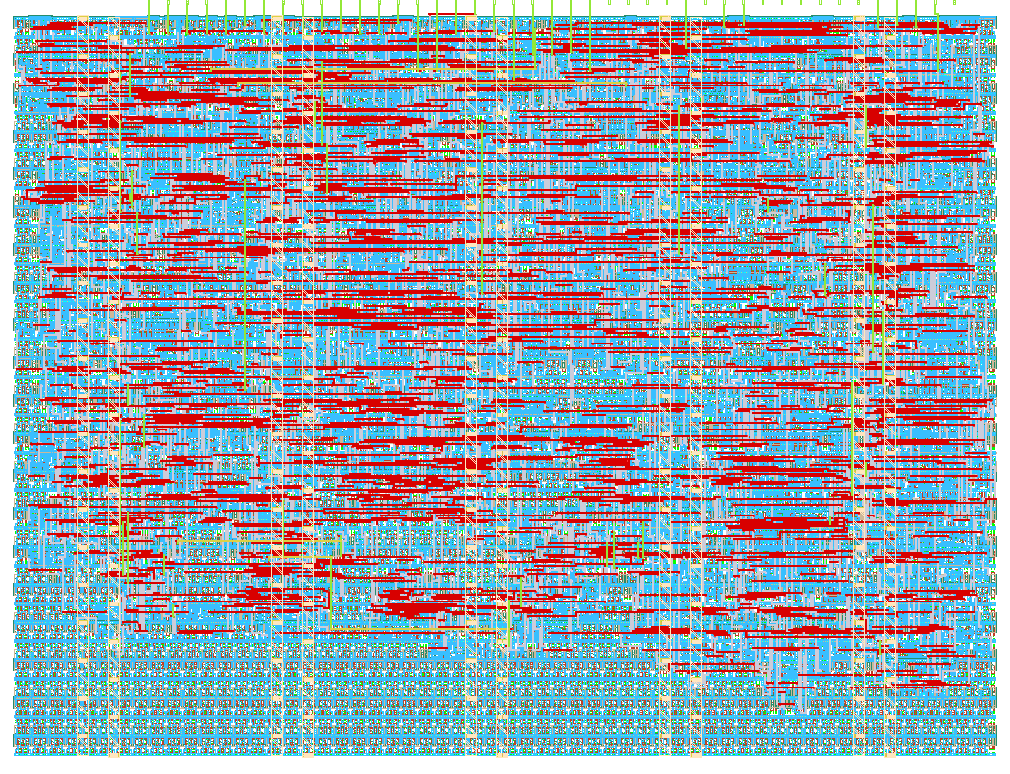
- Author: Marco Flückiger
- Description: Open-loop lock-in demodulator for the digital readout electronics of a single-axis laser gyroscope (fiber-optic interferometer)
- GitHub repository
- Open in 3D viewer
- Open in Tiny Tapeout Explorer
- Clock: 0 Hz
How it works
This design implements the digital readout electronics for a single-axis laser gyroscope (fiber-optic interferometer) using an open-loop lock-in demodulator architecture.
A configurable square-wave modulator (mod_ref_gen) generates the phase modulation reference signal, which drives an external phase modulator via uo_out[0]. The signal toggles every period clock cycles, so the full square-wave period is 2 × period. uo_out[1] (window_done) emits a one-clock pulse every period cycles, i.e. once per half-cycle of the modulation reference.
The returning interferometer signal is digitized by an external 1-bit Delta-Sigma ADC and fed into ui_in[0]. The lock-in demodulator (lockin_demod) correlates the incoming bitstream with the modulation reference: it adds +1 per clock when the bit equals the reference and −1 otherwise. The result is accumulated over one modulation half-cycle (period clocks) and latched into demod_out at the end of each window.
Output scaling: the accumulator magnitude is bounded by period (max. 2^16−1). Since demod_out is a signed 16-bit value, periods up to 32767 clocks are transferred losslessly (no scaling shift); above that the output saturates at ±32767 instead of wrapping. Example: period = 1000 → full-scale reading ±1000 corresponds to a fully correlated/anticorrelated bitstream.
While ui_in[1] (Enable) is low, the accumulator and demod_out hold their values — useful for reading a single measurement over SPI without it changing mid-transfer.
An SPI slave interface (spi_slave, SPI mode 0, MSB first) provides register access:
- Reg 0: modulation period (read/write, default: 1000)
- Reg 1: demodulator output
demod_out(read-only)
Protocol: 3-byte transfer. Command byte: bit 7 = read(1)/write(0), bit 0 = register address; then data-high and data-low bytes.
Examples:
0x00 0x00 0x14→ write Reg 0 = 20 (half-period = 20 clocks)0x80 0x00 0x00→ read Reg 0 (MISO returns current period)0x81 0x00 0x00→ read Reg 1 (MISO returns 16-bitdemod_out, MSB first, during bytes 2 and 3)
How to test
- Apply a clock to
clkand assertrst_n(active-low reset). - Set
ui_in[1](Enable) high to activate the design. - Feed a 1-bit Delta-Sigma stream into
ui_in[0]. - Observe the square-wave modulation reference on
uo_out[0]. - The heartbeat LED on
uo_out[2]toggles at approximately 1 Hz (at 10 MHz clock) when the design is running. - Use SPI (mode 0) to read the demodulated result:
- Assert
CS_N(active low) - Send 3 bytes: command
0x81(read Reg 1), then two dummy bytes - Capture MISO during bytes 2 and 3 for the 16-bit
demod_out - Optional: clear Enable after a
window_donepulse to freeze the result before reading
- Assert
External hardware
- External 1-bit Delta-Sigma ADC (photodiode frontend: TIA + comparator, or a ΔΣ modulator IC such as AD7401/AMC1306)
- External fiber-optic phase modulator driven by
uo_out[0]— the low-cost option is a piezo (PZT) fiber stretcher, see hardware.md - SPI master (microcontroller or FPGA) for register readout; example:
examples/host_readout.py
IO
| # | Input | Output | Bidirectional |
|---|---|---|---|
| 0 | Delta-Sigma bitstream from photodiode ADC | Modulation reference (square wave) | SPI SCK |
| 1 | Enable (high = active) | Window done pulse (1x per modulation cycle) | SPI MOSI |
| 2 | Heartbeat LED (~1 Hz) | SPI MISO | |
| 3 | SPI CS_N (active low) | ||
| 4 | |||
| 5 | |||
| 6 | |||
| 7 |