394 Async FIFO with CDC + PWM Peripheral
394 : Async FIFO with CDC + PWM Peripheral
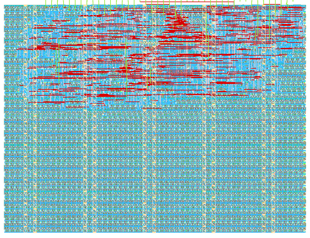
- Author: NUAT Labs
- Description: 8-deep async FIFO with Gray-code CDC and live 7-seg occupancy display, plus a small reusable PWM peripheral
- GitHub repository
- Open in 3D viewer
- Open in Tiny Tapeout Explorer
- Clock: 0 Hz
How it works
This project packs two independent digital blocks into one Tiny Tapeout tile:
1. Async FIFO with Gray-code CDC. An 8-entry, 4-bit-wide FIFO whose write side and read side can run on two completely independent, unrelated clocks. Correctness across the clock-domain crossing is guaranteed by the classic Gray-coded pointer + 2-flop synchronizer technique: both the write and read pointers are kept in both binary (for arithmetic) and Gray-code (for safe crossing, since only one bit ever changes between consecutive values) form, and each domain sees the other domain's Gray pointer only after it has passed through two back-to-back flip-flops. The current occupancy (0-8) is shown live on a 7-segment display.
2. PWM peripheral. A free-running 8-bit counter compared against a 4-bit duty register produces a 16-step PWM waveform. The duty value is loaded from a 4-bit input bus on a load pulse. It's deliberately written as a small, self-contained, reusable block -- the same RTL is a candidate to be dropped straight into a larger RISC-V SoC later as a memory-mapped timer/PWM peripheral.
How to test
No extra hardware needed (recommended first test):
- Set
ui_in[4] = 1(read domain uses the main devkit clock -- a synchronous fallback mode, so you don't need a second clock source). - Put a 4-bit value on
uio_in[3:0], pulseui_in[0]high for one clock to write it into the FIFO. Watch the 7-segment display (uo_out[6:0]) count up. - Pulse
ui_in[1]high to read a word back out (available onuio_out[7:4]); watch the 7-segment count back down. - To exercise the PWM block: put a duty value (0-15) on
uio_in[3:0], pulseui_in[2]to load it, then setui_in[3] = 1to enable.uo_out[7]will show the PWM waveform (scope or LED).
True async CDC test (needs a second clock source):
- Set
ui_in[4] = 0. - Feed an independent clock into
ui_in[7](a second RP2040/Pico GPIO, a bench signal generator, or even a slow hand-toggled switch both work) -- this becomes the FIFO's read-domain clock. - Write on the main clock as above, read using
ui_in[1]pulses timed to the external clock onui_in[7]. The occupancy display correctly lags by a couple of read-clock edges after each write -- that lag is the CDC synchronizer working as intended, not a bug.
External hardware
None required for the basic demo (everything above runs on the stock
Tiny Tapeout devkit's switches, LEDs and 7-segment display). For the
true asynchronous CDC demonstration, an external clock source wired
into ui_in[7] is optional but recommended.
IO
| # | Input | Output | Bidirectional |
|---|---|---|---|
| 0 | fifo_wr_en | SEG_A | fifo_wr_data[0] / pwm_duty_in[0] |
| 1 | fifo_rd_en | SEG_B | fifo_wr_data[1] / pwm_duty_in[1] |
| 2 | pwm_duty_load | SEG_C | fifo_wr_data[2] / pwm_duty_in[2] |
| 3 | pwm_enable | SEG_D | fifo_wr_data[3] / pwm_duty_in[3] |
| 4 | fifo_rd_clk_sel (1=use main clk, 0=use ui_in[7]) | SEG_E | fifo_rd_data[0] (output) |
| 5 | SEG_F | fifo_rd_data[1] (output) | |
| 6 | SEG_G | fifo_rd_data[2] (output) | |
| 7 | ext_rd_clk (optional 2nd clock for true CDC demo) | pwm_out | fifo_rd_data[3] (output) |