136 Timing-Prediction Test Vehicle
136 : Timing-Prediction Test Vehicle
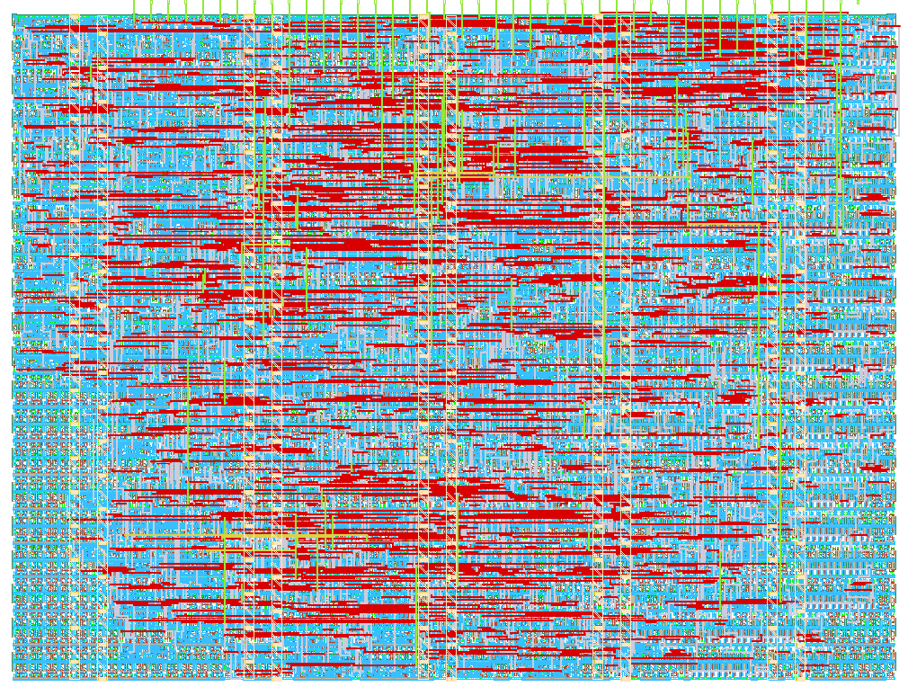
- Author: ECHO-HELLO-WORLD424
- Description: Half-cycle self-checking arithmetic timing-failure test vehicle with ring-oscillator delay canaries (pre/post-silicon timing-prediction study on IHP SG13G2)
- GitHub repository
- Open in 3D viewer
- Open in Tiny Tapeout Explorer
- Clock: 10000000 Hz
Submitted normal operation: 10 MHz, 50% duty (100 ns period). The 10–50 MHz research sweep deliberately exceeds that timing-safe specification. The design is verified: local hardening, RTL, GL and precheck pass, and canonical CI is all green (GDS run
35034979531); verification is tracked in the attempt log. Earlier physical results below remain historical evidence; fresh results are indata/safe10/.
How it works
A timing-prediction test vehicle for the IHP SG13G2 open PDK. It contains:
- DUT: a 16-bit ripple-carry adder split into four 4-bit segments. The carry between segments (and the final carry-out) passes through configurable inverter-pair delay banks (taps at 0/16/32/48 pairs), giving programmable critical-path lengths for a rising-launch/falling-capture timing experiment. Worst-case carry propagation is operand dependent, so the first-failure frequency depends on the applied pattern.
- Oracle: an independent combinational reference adder recomputes the expected result. It is compared at the next frame boundary, after operands have been held for 19 cycles; the deliberately delayed DUT is captured much earlier.
- Canaries: two ring-oscillator delay proxies - a generic inverter-line RO and a
structure-matched RO (looping through delay-bank + full-adder segments like the DUT) -
each with a 16-bit ripple edge counter over a configurable window (2^8..2^14 cycles).
The window is one-shot per reset:
win_doneis cleared only byrst_n, so the ring stops when the window closes and the counter holds its value until the next reset. Take one canary sample per reset rather than treating the count as continuous telemetry. The effective gate-open interval is(window cycles - 3)external clock periods - the three boot cycles before the configuration commits do not count - i.e. 25.3 us at 10 MHz and 5.06 us at 50 MHz for the 2^8 window. - Measurement: one timed operation per 19-cycle frame, 16-bit error and op counters (both saturating), first-error DUT byte capture, serial byte readout with an auto-incrementing pointer, a freeze input, and FORCE_ERR/FORCE_CAN DFT bits that make the error-accounting path itself testable before tapeout.
Config word (16-bit, driven during reset and held through the third rising edge after reset release, when it is committed): [1:0]/[3:2]/[5:4]/[7:6] = delay bank taps per segment, [9:8] = pattern (0=PRBS, 1=worst-case carry, 2=carry-free alternating, 3=static hold), [11:10] = canary select, [13:12] = window select, [14] = force canary mask, [15] = force DUT error.
The DUT launches operands on a rising edge and samples exactly once on the immediately following falling edge. Clock HIGH time is the measurement aperture: 10 ns at 50 MHz/50% duty, not the full 20 ns period. A failed first sample holds until comparison. Frequency sweeps must record actual high time and duty cycle.
FREEZE blocks new launches. An already launched operation completes its pending falling-edge capture even if FREEZE rises during the high phase. Keep clocking for two complete cycles after asserting FREEZE before reading. Resume never repeats a capture. Maintain the normal clock waveform through the pending falling edge.
ui[7] has no on-chip synchronizer, so the host must transition it as if it were
synchronous: assert or release FREEZE during the clock HIGH phase. That leaves
between half and one full clock period of settling ahead of the edge that samples it -
50-100 ns at 10 MHz, 10-20 ns at 50 MHz - comfortably beyond the 4 ns input-path budget
src/pnr.sdc already assumes with set_input_delay 4.0000 on ui_in[7]. A host that
can only act in the LOW phase must still land the transition at least 20 ns (10 MHz) or
10 ns (50 MHz) before the next rising edge, and prove it on a scope. FREEZE must be
generated in the chip's clock domain (host FPGA register, PIO, or equivalent hardware);
an OS-scheduled software GPIO write does not bound its own jitter to that window and is
not an acceptable source. A transition landing inside the setup/hold aperture of a
rising edge can make update_en resolve differently per register, which corrupts the
19-cycle frame alignment and can count a fabricated error. The normative rule, its scope
check, and the exclusion policy are in
the post-silicon protocol.
How to test
- Hold
rst_nlow and drive the config word onui[7:0](LSB) anduio[7:0](MSB). Releaserst_nduring the clock LOW phase before the first counted rising edge. Keep the config word stable through the third rising edge after releasingrst_n(the on-chip boot counter commits it at that edge), then setui[7]low - obeying the FREEZE transition rule above - and release youruiodrivers within the following clock period. The chip takes over theuiobus on the fourth rising edge; holding your drivers past it makes both sides drive the pads, causing bus contention. Configuration is already latched at that point; subsequentuiovalues do not update it. - Run the experiment at the target clock frequency/voltage/temperature for a known number of operations (19 cycles each). Start at 1.20 V/ambient and a low clock frequency. Record the clock high time as well as frequency.
- Set
ui[7]high during the clock HIGH phase (the FREEZE transition rule above), allow two complete clocks for pending capture and ripple settling, then read the 16 status bytes:uio[7:0]is the data byte selected byuo[3:0](auto-incrementing pointer). Byte map: 0-1 = DUT error count (saturating), 2-3/4-5 = generic/matched RO edge counts (16-bit, wrap mod 65536 -- telemetry, not saturating), 6-7 = operation count (saturating; it counts launches, so completed comparisons aremax(ops_cnt - 1, 0)and using the raw count as the denominator biases every error rate low; once saturated, the true count is>= 65535and no longer recoverable from this byte), 8 = segment-tap echo{seg3, seg2, seg1, seg0}; 9 = status flags{1, mat_ro_dead, gen_ro_dead, err_seen, can_sel[1:0], win_sel[1:0]}(can_selis bits 3:2,win_selis bits 1:0, and bit 7 is 1); 10 = low 8 bits of the first failed DUT result capture; 11-15 = 0. While frozen,uo[7:4]={frame_strobe, mat_ro_dead, gen_ro_dead, dut_err}. - Repeat across frequency/voltage/temperature; compare
f(error)contours against the RO telemetry and static timing analysis.
External hardware
A controller that can drive the clock from ~1-50 MHz, hold/step the config pins, and read the status pins (e.g. the Tiny Tapeout demo board or an FPGA host). For the PVT sweep: a variable core-voltage supply (verified accessible per Tiny Tapeout IHP powering rules) and a temperature chamber or controlled hot/cold plate. An external low-jitter clock source with characterized duty cycle is recommended near the timing boundary. Elevated temperature is optional and subject to fixture/assembly limits; 125 °C is a library corner, not a required test condition or a certified board rating.
IO
| # | Input | Output | Bidirectional |
|---|---|---|---|
| 0 | cfg_seg0[0] (reset) / unused (run) | ro_ptr[0] | cfg[8] (reset in) / status[0] (run out) |
| 1 | cfg_seg0[1] (reset) / unused (run) | ro_ptr[1] | cfg[9] (reset in) / status[1] (run out) |
| 2 | cfg_seg1[0] (reset) / unused (run) | ro_ptr[2] | cfg[10] (reset in) / status[2] (run out) |
| 3 | cfg_seg1[1] (reset) / unused (run) | ro_ptr[3] | cfg[11] (reset in) / status[3] (run out) |
| 4 | cfg_seg2[0] (reset) / unused (run) | dut_err (live) | cfg[12] (reset in) / status[4] (run out) |
| 5 | cfg_seg2[1] (reset) / unused (run) | gen_ro_dead | cfg[13] (reset in) / status[5] (run out) |
| 6 | cfg_seg3[0] (reset) / unused (run) | mat_ro_dead | cfg[14] (reset in) / status[6] (run out) |
| 7 | cfg_seg3[1] (reset) / FREEZE (run, active high) | frame_strobe | cfg[15] (reset in) / status[7] (run out) |