391 UART SPI RAM Loader
391 : UART SPI RAM Loader
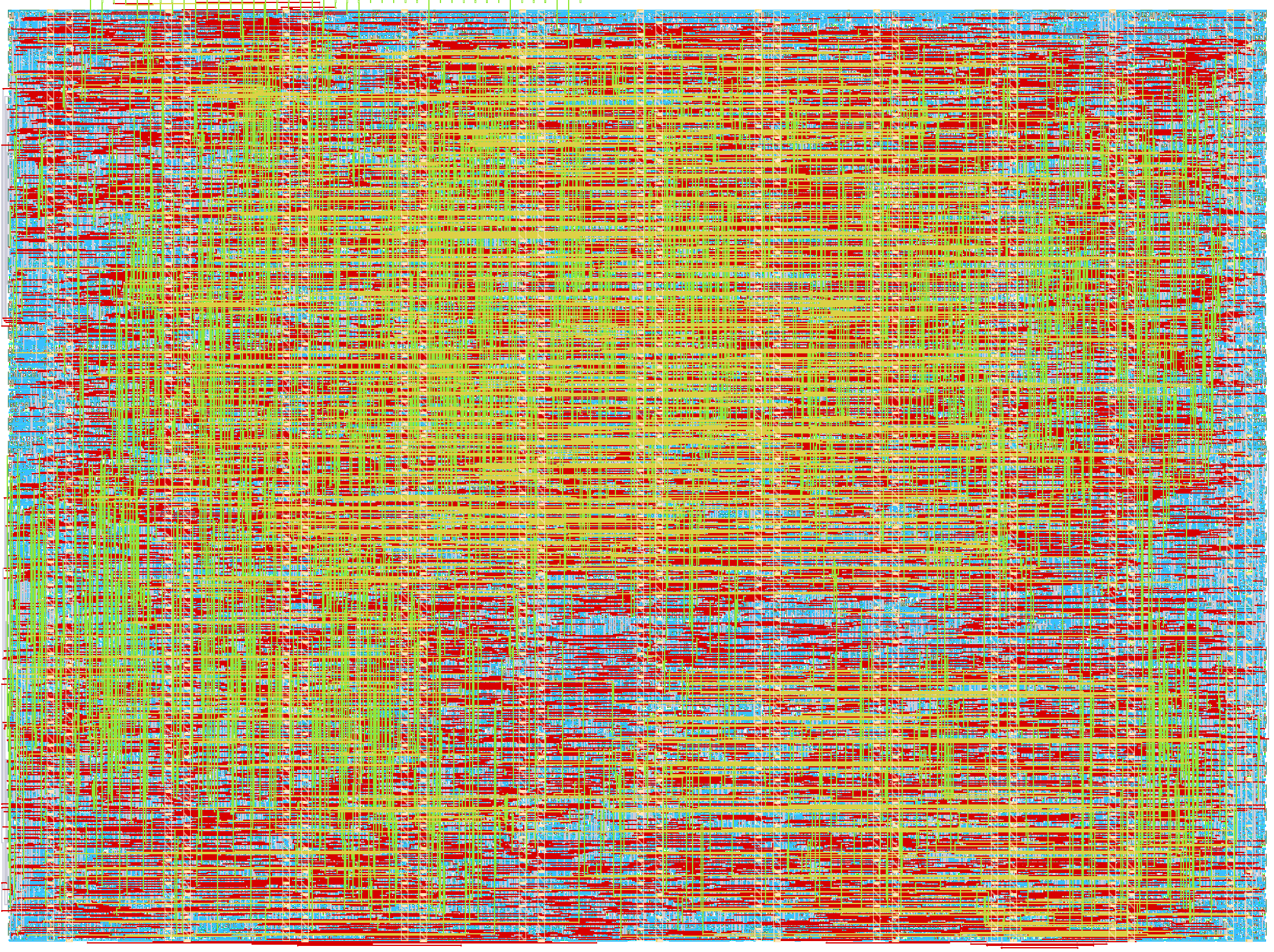
- Author: romd
- Description: CRC-protected UART loader for a 64 KiB SPI SRAM
- GitHub repository
- Open in 3D viewer
- Open in Tiny Tapeout Explorer
- Clock: 50000000 Hz
How it works
The design exposes every byte of a 23LC512-compatible 64 KiB SPI SRAM through a bounded, CRC-protected UART protocol. It runs from the 50 MHz project clock, uses 115200 baud 8N1 UART, and drives the SRAM in SPI mode 0 at 6.25 MHz.
After reset, the controller writes sequential mode (WRMR 40) and reads the
mode register back. Wait for uo_out[0] to go high before sending memory
commands. Reset reinitializes the controller but does not erase SRAM contents.
If mode verification fails, uo_out[7] goes high and memory commands return a
memory-fault response.
How to test
-
Select the project and provide a 50 MHz clock.
-
Connect the SRAM as shown below, then pulse active-low reset.
-
Wait for
uo_out[0](memory ready) to go high. -
Open the demoboard USB serial port at 115200 baud, 8N1, with no flow control.
-
Clone the project repository, install PySerial, and run the host CLI from the repository root. The CLI is
tools/uart_loader.py.python -m pip install pyserial==3.5 python tools/uart_loader.py --port COM4 ping python tools/uart_loader.py --port COM4 status python tools/uart_loader.py --port COM4 write 0x100 0x12 0x34 python tools/uart_loader.py --port COM4 read 0x100 2 python tools/uart_loader.py --port COM4 load firmware.bin python tools/uart_loader.py --port COM4 verify firmware.bin
Replace COM4 with the demoboard serial port, such as /dev/ttyACM0 on
Linux. The default maximum transfer is 16 bytes; the host queries the actual
limit with CAPABILITIES and chunks larger operations automatically.
The complete wire contract, error codes, CRC definition, and worked PING
vector are in the repository protocol documentation.
Requests start with A5 5A; responses start with 5A A5. Both use
CRC-16/CCITT-FALSE over the version-through-payload bytes.
External hardware
Connect a 23LC512-compatible SRAM at a voltage compatible with the demoboard:
| Project pin | Direction | SRAM signal |
|---|---|---|
uio[0] |
output | CS, active low |
uio[1] |
output | SI / MOSI |
uio[2] |
input | SO / MISO |
uio[3] |
output | SCK |
Connect common power and ground, and hold the SRAM HOLD input high when the
hold function is unused. UART RX is ui_in[3]; UART TX is uo_out[4]. These
are the demoboard USB serial receive and transmit paths, respectively.
Status outputs
| Output | Meaning |
|---|---|
uo_out[0] |
SRAM initialization succeeded |
uo_out[1] |
Memory transaction active |
uo_out[2] |
Sticky UART framing error |
uo_out[3] |
UART receive FIFO has capacity |
uo_out[4] |
UART TX |
uo_out[5] |
Sticky UART receive overrun |
uo_out[6] |
Sticky protocol validation error |
uo_out[7] |
SRAM initialization fault |
The sticky error outputs clear on electrical reset.
Layout
IO
| # | Input | Output | Bidirectional |
|---|---|---|---|
| 0 | Unused | SPI memory ready | SPI SRAM chip select, active low |
| 1 | Unused | Memory transaction active | SPI SRAM MOSI |
| 2 | Unused | UART framing error | SPI SRAM MISO |
| 3 | UART RX | UART RX has capacity | SPI SRAM clock |
| 4 | Unused | UART TX | Unused |
| 5 | Unused | UART RX overrun | Unused |
| 6 | Unused | Protocol error | Unused |
| 7 | Unused | SPI memory fault | Unused |