160 SENT to I2C bridge
160 : SENT to I2C bridge
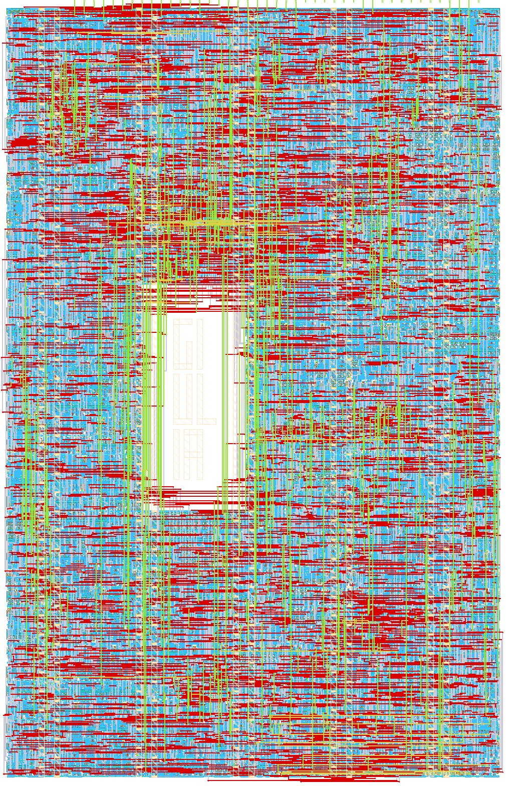
- Author: Enzo Nappi
- Description: Full-duplex SAE J2716 SENT decoder + encoder bridged to an I2C register-map slave
- GitHub repository
- Open in 3D viewer
- Open in Tiny Tapeout Explorer
- Clock: 10000000 Hz
How it works
This chip is a full-duplex bridge between a single-channel SENT (SAE J2716) automotive sensor link and I2C.
Receive path: a SENT decoder listens on ui[0]. It auto-calibrates the tick length from
each frame's sync pulse (no fixed tick assumed), then decodes a status nibble, 1-6 data
nibbles (configurable), and a CRC-4 nibble (poly x^4+x^3+1, seed 5, per SAE J2716). An optional
pause pulse after the CRC can be skipped so it is never mistaken for the next frame's sync.
Transmit path: an independent SENT encoder runs concurrently on uo[4], generating a
second, runtime-configurable SENT frame (own tick length, nibble count, optional padding to a
fixed frame duration) completely decoupled from the receiver — true full duplex, not
time-multiplexed.
Both sides are exposed through a single I2C slave (address 0x50, no clock stretching)
with an auto-incrementing register pointer: write one byte to set the pointer, then read (or
write, for writable registers) as many bytes as needed, wrapping at the top of the map. STATUS
is clear-on-read for its sticky error/new-data bits. The register map (20 registers,
0x00-0x13) covers, in order: received STATUS/STATUS_NIBBLE/DATA0-2/CRC/FRAME_COUNT and RX
CONFIG (0x00-0x07); the TX payload/CONFIG/TICK/FRAME_DUR registers (0x08-0x0F); and two
16-bit registers, SYNC_MIN and SYNC_MAX (0x10-0x13), that bound how long a pulse must be to
be accepted as a sync pulse — retunable at runtime for a different sensor tick length, with no
recompile needed.
A shadow snapshot publishes STATUS_NIBBLE/DATA/CRC only when no I2C transaction is in progress, so a multi-byte read is never torn between two different SENT frames.
How to test
Wire a SENT source to ui[0] (a real sensor, or the transmit output of a second instance of
this same chip looped back for a quick self-test) and an I2C master (address 0x50,
open-drain uio[1]=SDA / uio[0]=SCL, external pull-ups required — no clock stretching).
- Write
0x07(CONFIG) if you need to invert the input, enable the pause pulse, or change the expected data-nibble count from the 6-nibble default. - Point the register pointer at
0x00and read:STATUS,STATUS_NIBBLE,DATA0,DATA1,DATA2,CRC,FRAME_COUNT— a 7-byte block read pulls one full decoded frame.STATUSbit0 (new_data) tells you a frame has arrived since the last time you read it. - To transmit, write the payload to
TX_STATUS_NIBBLE/TX_DATA0-2(0x08-0x0B), then writeTX_CONFIG(0x0C) with bit0 (tx_enable) set — frames start going out onuo[4]immediately, back-to-back. - If your sensor's tick length is outside the 1-6 us default window, write the new bounds
(in raw clk cycles) to
SYNC_MIN_L/H/SYNC_MAX_L/H(0x10-0x13) before expecting a lock.
The RTL testbench (test/tb_sent_i2c.v, Icarus Verilog) exercises the decoder, encoder,
inverted polarity, the pause pulse, full-duplex RX-while-TX, and sync-mode frame padding
end to end and is the fastest way to check a change hasn't broken anything.
External hardware
Any single-channel SENT sensor (or a second instance of this chip, transmit side, for a
loopback bench test) on ui[0], and an I2C master with two 4.7kΩ pull-ups to 3.3V on
SCL/SDA. No other external hardware is required.
IO
| # | Input | Output | Bidirectional |
|---|---|---|---|
| 0 | SENT signal in (receive) | new_data (STATUS bit0, live) | I2C SCL (input only, no clock stretching) |
| 1 | crc_error (STATUS bit1, live) | I2C SDA (open-drain) | |
| 2 | sync_error (STATUS bit2, live) | ||
| 3 | frame_busy | ||
| 4 | SENT signal out (transmit) | ||
| 5 | tx_busy | ||
| 6 | |||
| 7 |