549 Morse Tree LED Decoder
549 : Morse Tree LED Decoder
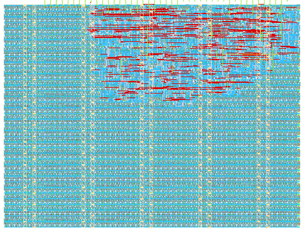
- Author: Matthias Wegmann
- Description: Reads a Morse key and lights the matching node of the Morse code tree on an 8x8 LED matrix
- GitHub repository
- Open in 3D viewer
- Open in Tiny Tapeout Explorer
- Clock: 10000000 Hz
How it works
The design listens to a Morse key on ui[0] and walks the Morse code binary tree:
every dot goes to the left child, every dash to the right child. The current tree
node is shown on an 8x8 LED matrix, one LED at a time. If you glue the LEDs onto a
poster of the Morse tree (with the letter written next to each LED), the light wanders
down the tree while you key a character and stops on the decoded letter.
Tree nodes are numbered like a binary heap: the root is 1 and each symbol appends one
bit (node = node * 2 + symbol, dot = 0, dash = 1). The 6-bit node number selects the
LED: node[5:3] is the row (uo_out, one-hot, active high) and node[2:0] is the
column (uio_out, one-hot, active low). Node 1 (root) is the "ready" LED, node 0 is an
error LED (more than five symbols).
Timing is measured in units of the dot length. The dot length is 2^SPEED base ticks,
one base tick being 2^15 clock cycles (3.3 ms at 10 MHz):
SPEED (ui[3:1]) |
0 | 1 | 2 | 3 | 4 | 5 | 6 | 7 |
|---|---|---|---|---|---|---|---|---|
| dot length @ 10 MHz | 3.3 ms | 6.5 ms | 13 ms | 26 ms | 52 ms | 105 ms | 210 ms | 420 ms |
- key pressed shorter than 2 units = dot, 2 units or longer = dash
- key released for 2 units = character complete (the LED stays on the letter)
- key released for 8 units = back to the root (unless
HOLD= 1, then the letter stays until the next key press)
Hand keying works well with SPEED 5 or 6. SPEED 0 and 1 are only meant for machine keying, because the ~3 ms debounce filter would swallow such short dots. Other clock frequencies scale all times accordingly (e.g. 20 MHz halves every value).
The key input is synchronised and debounced (stable for about 3 ms). KEY_INV (ui[7])
inverts the key, so a button to GND with a pull-up resistor can be used directly.
RAW (ui[5]) switches uo_out from the row one-hot code to the plain node number:
uo[5:0] = node, uo[6] = character complete, uo[7] = debounced key. This is handy
for testing from the demo board or for driving an external decoder instead of the matrix.
LED positions
| Node | Char | Code | Row (uo) | Col (uio) |
|---|---|---|---|---|
| 0 | (error) | more than 5 symbols | 0 | 0 |
| 1 | (root) | idle / keying | 0 | 1 |
| 2 | E | . |
0 | 2 |
| 3 | T | - |
0 | 3 |
| 4 | I | .. |
0 | 4 |
| 5 | A | .- |
0 | 5 |
| 6 | N | -. |
0 | 6 |
| 7 | M | -- |
0 | 7 |
| 8 | S | ... |
1 | 0 |
| 9 | U | ..- |
1 | 1 |
| 10 | R | .-. |
1 | 2 |
| 11 | W | .-- |
1 | 3 |
| 12 | D | -.. |
1 | 4 |
| 13 | K | -.- |
1 | 5 |
| 14 | G | --. |
1 | 6 |
| 15 | O | --- |
1 | 7 |
| 16 | H | .... |
2 | 0 |
| 17 | V | ...- |
2 | 1 |
| 18 | F | ..-. |
2 | 2 |
| 19 | Ü | ..-- |
2 | 3 |
| 20 | L | .-.. |
2 | 4 |
| 21 | Ä | .-.- |
2 | 5 |
| 22 | P | .--. |
2 | 6 |
| 23 | J | .--- |
2 | 7 |
| 24 | B | -... |
3 | 0 |
| 25 | X | -..- |
3 | 1 |
| 26 | C | -.-. |
3 | 2 |
| 27 | Y | -.-- |
3 | 3 |
| 28 | Z | --.. |
3 | 4 |
| 29 | Q | --.- |
3 | 5 |
| 30 | Ö | ---. |
3 | 6 |
| 31 | CH | ---- |
3 | 7 |
| 32 | 5 | ..... |
4 | 0 |
| 33 | 4 | ....- |
4 | 1 |
| 35 | 3 | ...-- |
4 | 3 |
| 39 | 2 | ..--- |
4 | 7 |
| 47 | 1 | .---- |
5 | 7 |
| 48 | 6 | -.... |
6 | 0 |
| 56 | 7 | --... |
7 | 0 |
| 60 | 8 | ---.. |
7 | 4 |
| 62 | 9 | ----. |
7 | 6 |
| 63 | 0 | ----- |
7 | 7 |
All other nodes 32..63 are the remaining five-symbol codes (punctuation, prosigns,
accented letters); their node number is simply 1 followed by the five symbol bits.
How to test
- Apply a 10 MHz clock and release reset. With
ui_in = 0the root LED (row 0, column 1) is lit:uo_out = 0x01,uio_out = 0xFD. - Set the speed, e.g.
ui[3:1] = 5(dot = 105 ms), and connect a push button toui[0](or setui[7] = 1for an active-low button). - Key
.-(short, long): after the dot the E LED lights (row 0, column 2), after the dash the A LED (row 0, column 5). Pause for two units and the A stays lit; after eight units the root LED comes back. - For an automated check set
ui[5] = 1(RAW mode) and read the node number onuo[5:0];uo[6]tells you that a character is complete.
The cocotb test in test/test.py keys several characters (S, O, A, H, 5, 1, ...), checks the
node after every symbol, the character-complete flag, the word gap, the HOLD mode, the error
node, the matrix outputs and the inverted key input.
External hardware
- A push button or Morse key on
ui[0]. - Up to 64 LEDs wired as an 8x8 matrix: LED anodes to the row lines
uo[0..7], cathodes to the column linesuio[0..7], one series resistor (about 470 Ω) per column line. Because only one LED is on at any time, no multiplexing or driver ICs are needed; the chip pins can only supply a few mA, so use efficient (low-current) LEDs or add transistor drivers for brighter ones. - Instead of a matrix you can use RAW mode and feed the node number into external decoders.
IO
| # | Input | Output | Bidirectional |
|---|---|---|---|
| 0 | KEY (Morse key, 1 = pressed) | ROW0 / NODE0 | COL0 (active low) |
| 1 | SPEED[0] | ROW1 / NODE1 | COL1 (active low) |
| 2 | SPEED[1] | ROW2 / NODE2 | COL2 (active low) |
| 3 | SPEED[2] | ROW3 / NODE3 | COL3 (active low) |
| 4 | HOLD (keep last character until next key press) | ROW4 / NODE4 | COL4 (active low) |
| 5 | RAW (uo_out = {KEY, DONE, NODE[5:0]}) | ROW5 / NODE5 | COL5 (active low) |
| 6 | ROW6 / DONE | COL6 (active low) | |
| 7 | KEY_INV (1 = key is active low) | ROW7 / KEY | COL7 (active low) |