392 8N1 UART Transceiver
392 : 8N1 UART Transceiver
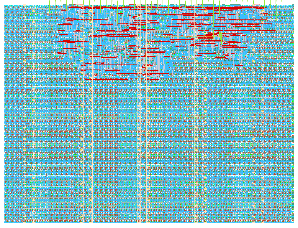
- Author: NUAT Labs
- Description: Full-duplex 8N1 UART transceiver (TX + RX) with runtime bidirectional data bus and mid-bit sampling
- GitHub repository
- Open in 3D viewer
- Open in Tiny Tapeout Explorer
- Clock: 0 Hz
How it works
The tt_um_nuatlabs_uart design is a full-duplex, 8N1 (8 data bits, no parity, 1 stop bit) Universal Asynchronous Receiver-Transmitter (UART) peripheral hardened on the 130nm IHP SG13G2 BiCMOS process via Tiny Tapeout. It fits into a single standard tile (1x1) and features a runtime time-multiplexed bidirectional data bus that allows full 8-bit parallel data transfer using Tiny Tapeout's 8 shared GPIO pins (uio).
Architecture Overview
                      +---------------------------------------+
                      |         tt_um_nuatlabs_uart           |
                      |                                       |
    ui_in[0] (rxd) -->|--> [2-Stage Sync] --> [UART RX]       |
                      |                           |           |
                      |                        rx_data        |
                      |                           |           |
    ui_in[1] (tx_st)->|---------------------> [UART TX]       |
                      |                           |           |
                      |                          txd -------->|--> uo_out[0] (txd)
                      |                        tx_busy ------>|--> uo_out[1] (tx_busy)
                      |                        rx_valid ----->|--> uo_out[2] (rx_valid)
                      |                                       |
    ui_in[2] -------->|-- [Bus Multiplexer & Dir Control]     |
 (uio_load_mode)      |       |                      ^        |
                      |       v                      |        |
                      |   tx_data_bus             rx_data     |
                      |       |                      |        |
                      +-------|----------------------|--------+
                              v                      |
                         uio[7:0] (Input)       uio[7:0] (Output)
-
UART Transmitter (
uart_tx):- Implemented as a clean 3-block Moore Finite State Machine (
ST_IDLE,ST_START,ST_DATA,ST_STOP). - Latches
tx_datafrom theuio_inbus upon detecting a single-cycle high pulse onui_in[1](tx_start). - Drives
uo_out[1](tx_busy) high throughout transmission. - Frames the byte by outputting a low start bit (0), shifting 8 data bits out (LSB first), and terminating with a high stop bit (1) onto
uo_out[0](txd). - Bit duration is governed by the parameter
BAUD_DIV = f_clk / baud_rate.
- Implemented as a clean 3-block Moore Finite State Machine (
-
UART Receiver (
uart_rx):- Asynchronous serial input
ui_in[0](rxd) passes through a 2-stage flip-flop synchronizer (rxd_sync1,rxd_sync2) to eliminate metastability risks. - Falling edge detection initiates the start bit sequence.
- Samples incoming data at the exact midpoint of each bit interval (
BAUD_DIV / 2), providing maximum noise immunity and tolerance against clock jitter. - Shifts incoming bits into an internal shift register (LSB first).
- Upon successful verification of the stop bit, latches the parallel byte into
rx_dataand assertsuo_out[2](rx_valid) for exactly one clock cycle.
- Asynchronous serial input
-
Time-Multiplexed Bidirectional Data Bus (
uio[7:0]):- Because standard Tiny Tapeout tiles provide 8 dedicated inputs, 8 dedicated outputs, and 8 bidirectional IOs, dedicating 16 separate pins for parallel TX and RX bytes is impossible.
- This design uses
ui_in[2](uio_load_mode) to dynamically govern the direction of the bidirectionaluiobank:- Load / Transmit Mode (
uio_load_mode = 1): Setsuio_oe = 8'h00(input mode). The external host or microcontroller presents the 8-bit byte to transmit onuio_in[7:0]. - Read / Display Mode (
uio_load_mode = 0): Setsuio_oe = 8'hFF(output mode). The chip drives the last successfully received byte ontouio_out[7:0].
- Load / Transmit Mode (
Baud Rate Configuration
The hardware divider is parameterized via BAUD_DIV = f_clk / baud_rate:
- In this build,
BAUD_DIVis defaulted to4for rapid, deterministic simulation in Cocotb. - For physical silicon running at a typical devkit clock (e.g., 50 MHz internal clock, or 10 MHz), set the external clock frequency or divider according to the target baud (e.g. 9600, 115200, 1Mbaud).
How to test
1. Verification in Simulation (Cocotb)
Run the automated test suite from the repository root:
cd test
make clean
make SIM=icarus
The testbench validates 3 comprehensive scenarios:
test_uart_tx_shape: Checks bit timing and serial frame shape: start bit (0), 8 data bits (LSB-first), stop bit (1), and active duration oftx_busy.test_uart_loopback_single_byte: Emulates an external jumper wire by dynamically copyinguo_out[0](txd) toui_in[0](rxd) cycle-by-cycle, verifying full transmission, reception, and reconstruction.test_uart_loopback_multiple_bytes: Stress tests back-to-back transmissions across boundary and alternating values (0x00,0xFF,0x55,0xAA,0x81,0x7E).
2. Physical Hardware Testing on Tiny Tapeout Devkit
A. Basic Bench Loopback Test (No External Tools Required)
- Connect a standard breadboard jumper wire between pin
uo[0](txd) and pinui[0](rxd). - Set DIP switch
ui[2](uio_load_mode) to1(input mode). - Set the 8 DIP switches on
uio[7:0]to the desired 8-bit test byte (e.g.,0xA5/10100101). - Pulse DIP switch or push button
ui[1](tx_start) high then low. - Observe
uo[1](tx_busy) LED toggle high while transmitting. - Observe
uo[2](rx_valid) LED pulse when reception completes. - Flip switch
ui[2](uio_load_mode) to0(output mode). - The 8 LEDs connected to
uio[7:0]will display the received byte, matching the byte sent in step 3.
B. Interfacing with a Host PC (USB-to-UART Adapter)
- Connect a 3.3V USB-to-UART bridge (FTDI, CP2102, or RP2040):
- PC TXD -> Tiny Tapeout
ui[0](rxd) - Tiny Tapeout
uo[0](txd) -> PC RXD - Common Ground (GND -> GND).
- PC TXD -> Tiny Tapeout
- Open a terminal (PuTTY, minicom, screen, or PySerial) at the baud rate configured for your clock frequency.
- Transmit characters from PC to chip or trigger transmissions from chip to PC.
External hardware
- Minimal Loopback Demo: A single jumper wire connecting
uo[0]toui[0]. - Host PC Interfacing: 3.3V USB-to-UART bridge adapter (CP2102, FT232R, or Raspberry Pi Pico).
IO
| # | Input | Output | Bidirectional |
|---|---|---|---|
| 0 | rxd (serial input) | txd (serial output) | tx_data[0] (in) / rx_data[0] (out) |
| 1 | tx_start (transmit start pulse) | tx_busy (transmitter busy flag) | tx_data[1] (in) / rx_data[1] (out) |
| 2 | uio_load_mode (1=load tx_data, 0=show rx_data) | rx_valid (receiver valid pulse) | tx_data[2] (in) / rx_data[2] (out) |
| 3 | tx_data[3] (in) / rx_data[3] (out) | ||
| 4 | tx_data[4] (in) / rx_data[4] (out) | ||
| 5 | tx_data[5] (in) / rx_data[5] (out) | ||
| 6 | tx_data[6] (in) / rx_data[6] (out) | ||
| 7 | tx_data[7] (in) / rx_data[7] (out) |