487 ieee_tt_tinyopt4
487 : ieee_tt_tinyopt4
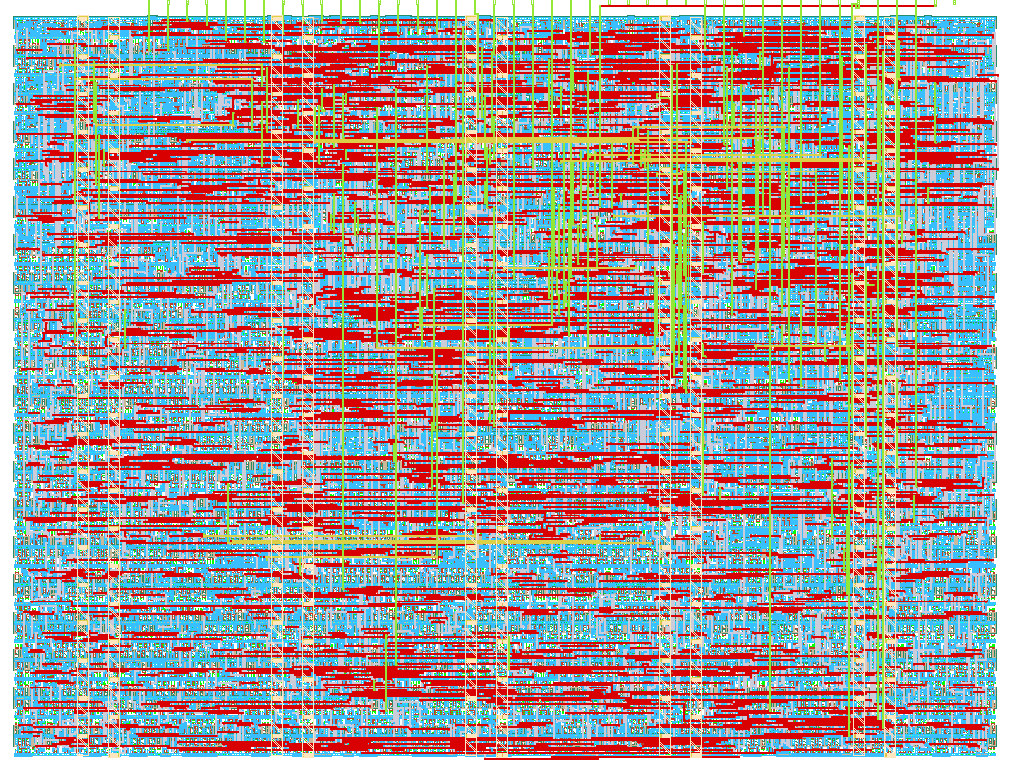
- Author: Berthyn Rodrigo Tinini Chuquimia
- Description: 4-tap LMS adaptive update engine for FIR system identification
- GitHub repository
- Open in 3D viewer
- Open in Tiny Tapeout Explorer
- Clock: 10000000 Hz
TinyOpt-4 LMS Engine
How it works
tt_um_tinyopt4 is a compact sequential parameter update engine designed specifically for adaptive FIR identification. The core executes an 11-state, time-multiplexed schedule with a 10-cycle processing path around a shared arithmetic unit:
- State
S_IDLE: Polls control bits; captures incoming data sample $x[n]$ into the 4-element shift register whenstart = 1anddata_sel = 0. - States
S_MAC0toS_MAC3: Feeds pairs $(w_i[n], x[n-i])$ sequentially into the single signed $8 \times 8$ multiplier. Products are added into the 18-bit accumulator. - State
S_ERR: Clamps the normalized accumulator to the 8-bit range $[-128, +127]$, subtracts this estimate from reference $d[n]$, and registers the bounded difference $e[n]$. - States
S_UPD0toS_UPD3: Re-routes the multiplier to compute $e[n] \cdot x[n-i]$. The 16-bit intermediate product passes through an arithmetic barrel shifter configured by $s$, saturates, and updates register $w_i[n+1]$. - State
S_DONE: Pulsesdonehigh for one cycle, deassertsbusy, and returns the FSM toS_IDLE.
How to test
Verification relies on the Cocotb test framework running under Icarus Verilog (iverilog):
- Target Verification Vector: Automated simulation feeds pseudo-random $Q1.7$ sequences through a static target plant $W^* = [64, -32, 16, -8]$.
- Pass/Fail Assertion: After 1500 consecutive update cycles, the test checks that all four hardware registers converge within $\vert{}w_i - W^*_i\vert{} \le 10\text{ LSB}$ to account for truncated intermediate precision.
- Gate-Level Check: The post-synthesis netlist generated by LibreLane is re-simulated using the same Cocotb harness to verify zero functional regression across cell delays.
How to use
Bus and Control Mapping
| Interface | Signal | Role |
|---|---|---|
ui_in[7:0] |
Data / Address | Input values ($x[n]$, $d[n]$, or shift exponent $s$). When idle, bits [2:0] act as register read address. |
uo_out[7:0] |
Data Out | Monitored byte selected by ui_in[2:0]. |
uio_in[0] |
start |
Clock-synchronous execution strobe. |
uio_in[1] |
data_sel |
0 = Shift sample $x[n]$; 1 = Latch reference $d[n]$ and trigger 10-cycle update. |
uio_in[2] |
cfg_sel |
1 = Write learning rate exponent $s$ from ui_in[2:0]. |
uio_out[4] |
busy |
Held high by FSM during the 10 processing cycles. |
uio_out[5] |
done |
Single-cycle pulse marking coefficient update completion. |
uio_out[6] |
overflow |
Latched high if prediction or error calculation exceeds $Q1.7$ limits. |
uio_out[7] |
w_sat |
Latched high if any tap update hits $\pm 127$ saturation bounds. |
Operational Procedure
- Reset Sequence: Assert
rst_n = 0for 3 clock cycles, then release (rst_n = 1). - Set Step Exponent (Optional): Drive
ui_in[2:0] = s(e.g.,3for $\mu = 2^{-3}$), pulseuio_in = 3'b101for one cycle, then returnuio_into0. - Feed History Buffer: For each of the initial samples, place $x[n]$ on
ui_in[7:0], strobeuio_in = 3'b001for one cycle, and wait one cycle. - Trigger Filter & Adaptation: Place $d[n]$ on
ui_in[7:0], strobeuio_in = 3'b011for one cycle, then clearuio_in = 0. - Monitor Flags: Wait 10 clock cycles until
uio_out[4](busy) returns low anduio_out[5](done) pulses high. - Readback Register: With
uio_in = 0, apply the target address toui_in[2:0]:
3'b000: Predicted response $\hat{y}[n]$3'b001: Error residual $e[n]$3'b010to3'b101: Filter taps $w_0$ to $w_3$
External hardware
None required. The module operates self-contained on any standard Tiny Tapeout carrier board:
- Manual Inspection: On-board DIP switches drive control/data lines; onboard LEDs display status flags and output bytes.
- Automated Benchmarking: Any standard 3.3V microcontroller (RP2040, ESP32) or USB-to-GPIO interface can drive the 8-bit parallel bus up to 10 MHz.
IO
| # | Input | Output | Bidirectional |
|---|---|---|---|
| 0 | Data input bit 0 (x / d / cfg_mu) | Multiplexed output bit 0 (y_hat / e / w0-w3) | In: start |
| 1 | Data input bit 1 | Multiplexed output bit 1 | In: data_sel (0=x, 1=d) |
| 2 | Data input bit 2 | Multiplexed output bit 2 | In: cfg_sel (1=config mu) |
| 3 | Data input bit 3 | Multiplexed output bit 3 | In: unused / tied low |
| 4 | Data input bit 4 | Multiplexed output bit 4 | Out: busy |
| 5 | Data input bit 5 | Multiplexed output bit 5 | Out: done |
| 6 | Data input bit 6 | Multiplexed output bit 6 | Out: overflow flag |
| 7 | Data input bit 7 | Multiplexed output bit 7 | Out: weight saturation flag |