719 Chrome Chain
719 : Chrome Chain
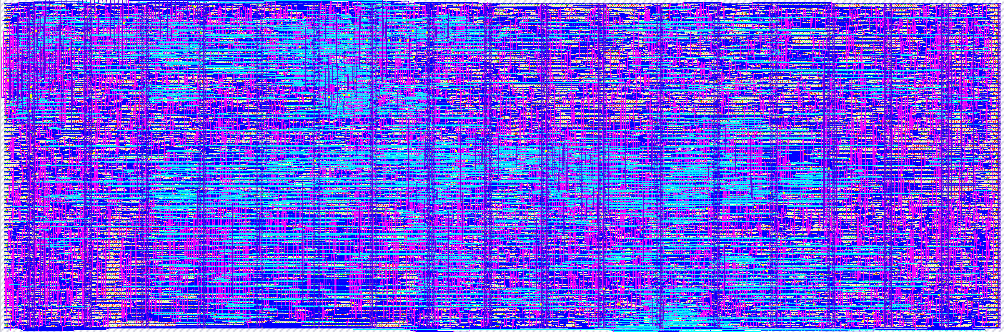
- Author: KU Leuven TT2026 Group 03
- Description: Ternary bit-serial MNIST classifier with a distribution-free conformal early exit
- GitHub repository
- Open in 3D viewer
- Open in Tiny Tapeout Explorer
- Clock: 10000000 Hz
How it works
Chrome Chain classifies handwritten digits from 8x8, 4-bit greyscale images using a ternary-weight neural network, and stops early — as soon as the answer is already decided — under a distribution-free conformal guarantee.
The network
64 inputs, 32 hidden units, 10 classes. Every weight is ternary (-1, 0, +1), so a
multiply collapses into a select-and-add: the L1 layer is a signed popcount rather than a
multiplier array. Hidden activations are 4-bit unsigned. The L2 layer consumes P = 4
hidden units per cycle, updating all 10 class scores each cycle, and its weights and
requantisation shifts live in small ROMs with four read ports.
Bit-serial, plane-major
Each pixel is 4 bits, so an image is four bitplanes presented MSB-first. The L1
accumulator folds them with Horner's rule — acc = 2*acc + plane_k — so no plane needs a
multiplier and the hidden accumulator stays 10 bits wide. Pixels are scanned one per
cycle, and a zero-skip mode can shorten a plane to its populated pixels.
The early exit
After each plane the partial scores pass through a two-stage comparator tree that yields the current argmax and its margin. If that margin clears the threshold for the checkpoint, the top FSM stops: no further plane is swapped in, and the cycles the remaining planes would have cost are never spent. Check latency is 11 cycles.
The thresholds are not hand-tuned. They come from a distribution-free conformal calibration, which is what lets the exit carry a stated error bound instead of a hope.
Resuming costs nothing. On "not done" the accumulators are never cleared, so plane k+1
adds to the work planes 1..k already did — the exit is anytime, not restart. Only
img_start zeroes the accumulator base.
Configuration
A 6-byte blob (48 bits, 43 in use) is written in before the first image and holds three
10-bit thresholds, per-checkpoint arm bits, per-plane inversion, the zero-skip enable, a
weight-page select, a per-plane valid-strobe enable, and N_cap — the maximum number of
planes to run. By default checkpoints 2 and 3 are armed and checkpoint 1 is disarmed.
Leave N_cap at 4: the checkpoint controller always waits for the fourth plane
boundary. Any other value is clamped to 4 and raises the N_cap alarm on DFT_SEL = 3
(and ERR), so a host that meant to run fewer planes sees why the chip is still
waiting for them.
Until the blob is loaded, START is ignored. A chip that classified with reset-value
thresholds would be silently wrong; this makes it visibly stalled instead.
Error reporting
Five sticky alarms — scheduling violation, scanner contract breach, torn frame, config
overrun, and out-of-range N_cap — are readable individually on DFT view 3. Each is the
loud version of a failure that would otherwise surface only as a bad answer, which on
returned silicon is the difference between a debug hour and a debug week.
How to test
All control lives on the bidirectional pins. ui_in[7:0] is the only wide data path and
carries both config words and pixel beats — never at the same time.
1. Reset. Hold rst_n low for a few cycles. With DFT_SEL = 0, uo_out reads back
0x20: LD_READY (uo[5]) is high because the fill buffer is empty, and BUSY, DONE
and ERR are all low.
2. Load the config blob. Raise CFG_MODE (uio[2]) and pulse CFG_STB (uio[3]) once
per byte with the byte on ui_in[7:0]. Six bytes. The loader owns the address counter, so
the host only has to count strobes. Then set DFT_SEL = 2 and check that uo_out[7]
(blob_loaded) has gone high, and DFT_SEL = 3 to confirm all five alarm bits are clear.
3. Start the image. Pulse START (uio[4]) for one cycle, then leave LD_EN low for
one more cycle. BUSY (uo[6]) goes high. The order matters: START clears the fill
buffer, so a plane loaded before START is discarded, and an image buffered entirely
before START hangs the chip.
4. Feed the image. Raise LD_EN (uio[0]) and present the image 8 bits per cycle: 8
beats per bitplane, 4 planes, MSB plane first, one beat per cycle only while LD_READY
(uo[5]) is high. If the per-plane valid strobe is enabled in the blob, pulse
LD_VSTROBE (uio[1]) with the last beat of each plane. When the answer is ready DONE
(uo[4]) pulses for one cycle with the predicted class on uo_out[3:0] as a value from 0
to 9, and BUSY falls.
The pixel scanner has no abort, so after an early exit it keeps running the plane it is
on for up to 52 cycles after BUSY falls. Wait that long before the next START, or
the next image's first plane is scanned before it is loaded and the scanner alarm
latches.
5. See where it exited. With DFT_SEL = 2, uo_out[2:0] carries exit_k — the
checkpoint the decision was taken at (2 or 3 with the default arming), or 0 when the
answer came from the final plane. On easy digits this is 2 rather than 0, and that
difference is the entire point of the design.
Output views
DFT_SEL (uio[6:5]) selects what uo_out reports:
DFT_SEL |
uo_out[7:0] |
|---|---|
| 0 | {ERR, BUSY, LD_READY, DONE, ANSWER[3:0]} — the operating view |
| 1 | the config word at the loader's address: the word about to be written mid-load, undefined after a complete load |
| 2 | {blob_loaded, ld_done, ld_idx[1:0], 0, exit_k[2:0]} |
| 3 | the five sticky alarms, individually |
The cocotb tests in test/ cover reset behaviour, the interlock that ignores START
before a blob is loaded, a full config blob load, a load aborted and restarted, and
three fixed images run end to end through the pins (an early exit at checkpoint 2, a
full four-plane run, and the same image with zero-skip), plus the N_cap alarm.
External hardware
None. The design needs only a host able to drive the 8-bit bus and the control pins — a microcontroller, an FPGA, or the RP2040 on the Tiny Tapeout demo board. No PMOD, display, or analog front end is required.
Outputs are plain logic levels, so four LEDs on uo_out[3:0] are enough to read the
predicted class directly: the answer is held until the next image. DONE on uo_out[4]
is a single-cycle pulse, so it needs a latch or a logic analyser rather than an LED.
IO
| # | Input | Output | Bidirectional |
|---|---|---|---|
| 0 | DATA0 | ANSWER0 | LD_EN |
| 1 | DATA1 | ANSWER1 | LD_VSTROBE |
| 2 | DATA2 | ANSWER2 | CFG_MODE |
| 3 | DATA3 | ANSWER3 | CFG_STB |
| 4 | DATA4 | DONE | START |
| 5 | DATA5 | LD_READY | DFT_SEL0 |
| 6 | DATA6 | BUSY | DFT_SEL1 |
| 7 | DATA7 | ERR | RESERVED |