879 Tiny ALU PD
879 : Tiny ALU PD
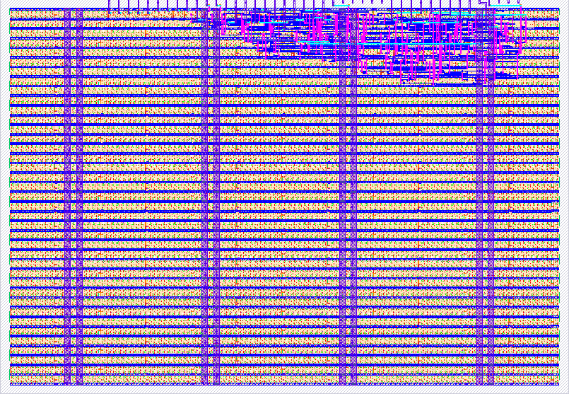
- Author: rangfuu
- Description: 4-bit ALU with hexadecimal 7-segment display and physical-design experiments
- GitHub repository
- Open in 3D viewer
- Open in Tiny Tapeout Explorer
- Clock: 0 Hz
How it works
This revision displays the 4-bit ALU result directly on the TinyTapeout demo
board's hexadecimal 7-segment display. It replaces the original binary-only
uo_out interface; binary result and zero flag are now on uio[7:3].
Inputs: ui_in[3:0] = A, ui_in[7:4] = B, uio_in[2:0] = opcode.
| Opcode | Operation | Result |
|---|---|---|
| 000 | ADD | (A + B) modulo 16 |
| 001 | SUB | (A - B) modulo 16 |
| 010 | AND | A & B |
| 011 | OR | A | B |
| 100 | XOR | A ^ B |
| 101 | SHL | A shifted left by one, truncated to 4 bits |
| 110 | SHR | A shifted right by one, zero filled |
| 111 | EQ | 1 if A equals B, otherwise 0 |
uo_out[6:0] drives active-high segments a,b,c,d,e,f,g in bit order 0..6.
The display shows 0..9,A,b,C,d,E,F. uo_out[7] is the decimal point:
it lights for ADD carry or SUB borrow (A < B), and is off for other operations.
uio_out[7:4] is the binary result; uio_out[3] is 1 when result is zero.
uio_oe = 0xF8: bits 0..2 are inputs; bits 3..7 are outputs.
This is a combinational circuit. No running clock or reset sequence is required.
How to test
Select tt_um_rangfuu_alu on the correct shuttle in TinyTapeout Commander.
Configure MCU bidirectional output enable to 0x07 (opcode pins only).
In MCU control mode, set ui_in=0x53 and opcode=0: 3 + 5 displays 8.
Set ui_in=0x1F: 15 + 1 displays 0 with the decimal point on.
Set ui_in=0x53, opcode=1: 3 - 5 displays E with the decimal point on.
For physical A/B switches, use ASIC_MANUAL_INPUTS mode: the lower four
input DIP switches select A, and the upper four select B. Opcode can remain
MCU-controlled, configured at boot, or be changed through the REPL.
For three external opcode switches, set MCU uio_oe_pico=0 and drive only
uio[2:0] from 3.3 V/GND with defined pull resistors. Do not drive uio[7:3].
The repository's demo/alu_demo.py provides setup(), show(a,b,op),
opcode(op) for DIP mode, and selftest() for all 2,048 input combinations.
The script reads actual chip outputs before checking them against its oracle.
Board testing is pending receipt of the revised silicon; simulation is not
a hardware test. demo/config.ini.example shows boot configuration.
The cocotb test exhaustively checks all 16 x 16 x 8 combinations, including segment encoding, carry/borrow, zero, binary result and output-enable direction.
External hardware
TinyTapeout demo board with its built-in common-cathode 7-segment display. No external display decoder is needed. Enable the board's segment connections if its revision has display jumpers. Optional: three opcode switches with pull resistors connected to the bidirectional header, or MCU/Commander control. In MCU control mode keep input DIP switches off as directed by the board guide.
References:
- https://tinytapeout.com/guides/get-started-demoboard/
- https://github.com/TinyTapeout/tt-demo-pcb
- https://github.com/TinyTapeout/tt-micropython-firmware
IO
| # | Input | Output | Bidirectional |
|---|---|---|---|
| 0 | A0 | segment_a | op0 |
| 1 | A1 | segment_b | op1 |
| 2 | A2 | segment_c | op2 |
| 3 | A3 | segment_d | zero (output) |
| 4 | B0 | segment_e | Y0 (output) |
| 5 | B1 | segment_f | Y1 (output) |
| 6 | B2 | segment_g | Y2 (output) |
| 7 | B3 | decimal_point_carry_borrow | Y3 (output) |