654 8-bit Modified RISC-V
654 : 8-bit Modified RISC-V
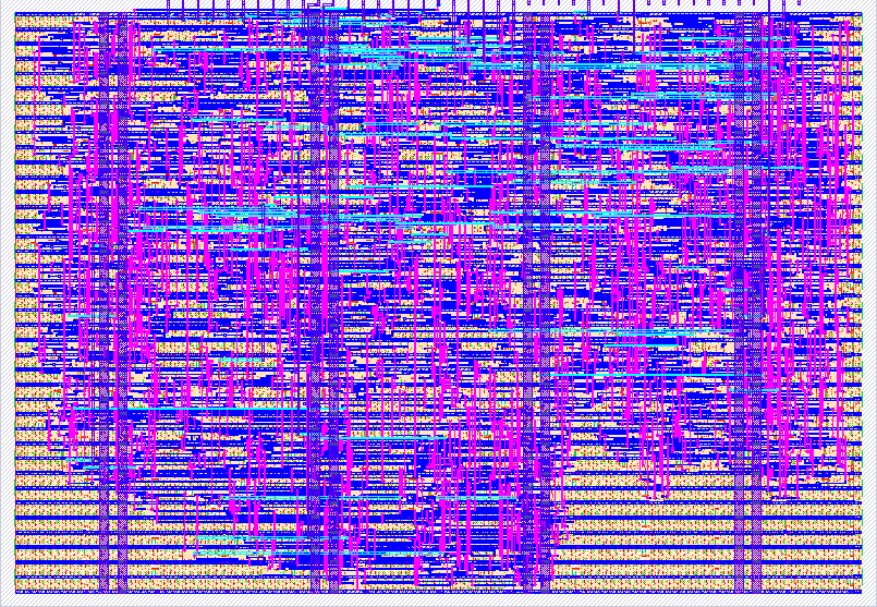
- Author: UCLA Digital Tapeout
- Description: An 8-bit modified RISC-V processor
- GitHub repository
- Open in 3D viewer
- Open in Tiny Tapeout Explorer
- Clock: 50000000 Hz
How it works
Our first project as a club was to tape out a modified 8-bit RISC-V-inspired ISA:
- 4 registers in the register file
- 4 instructions in instruction memory
- 1 register in data memory
Instruction encoding — a single instruction is 8 bits:
| Bits | Field | Description |
|---|---|---|
ins[7] |
Opcode | 0 = R-type, 1 = I-type |
ins[6:5] |
rd |
Destination register |
ins[4:3] |
rs2 / imm |
Second source register or immediate |
ins[2:0] |
ALU op | See ALU operations below |
ALU operations (defined in alu_ops.svh):
| Mnemonic | Encoding |
|---|---|
ADD |
3'b000 |
SUB |
3'b001 |
RIGHT_SHIFT |
3'b010 |
LEFT_SHIFT |
3'b011 |
AND |
3'b100 |
OR |
3'b101 |
XOR |
3'b110 |
WRITE |
3'b111 |
WRITE is a special case that doesn't modify register values — instead, it writes the value at address rd to the single register in data memory.
On reset, registers in the register file are initialized to a constant value: %0 = 0, %1 = 1, %2 = 2, %3 = 3 (always).
Modified data path diagram:
<img width="2640" height="1485" alt="image" src="https://github.com/user-attachments/assets/218b3759-b554-40ba-85e5-2e5075e3d50c" />
Communication
SPI MAC python script -> RP2040 (receive command and send SPI bytes)
                       -> SPI module (receive bytes packet and write to IMEM)
                       -> CPU (run program)
                       -> SPI module (read DMEM output)
                       -> RP2040 (send output to MAC python script)
- The RP2040 is the master; the SPI module is the slave.
- The SPI module receives a packet when the chip-select line is low, consisting of two bytes: byte 1 is the command/address byte, byte 2 is the data byte (if applicable).
Supported SPI commands:
| Command | Data | Action |
|---|---|---|
0x80 |
data |
imem[0] = data |
0x81 |
data |
imem[1] = data |
0x82 |
data |
imem[2] = data |
0x83 |
data |
imem[3] = data |
0x84 |
data |
Control register: data[0] = cpu_start, data[1] = cpu_step |
0x05 |
0x00 |
Read dmem_value on MISO (debug) |
0x06 |
0x00 |
Read pc_value on MISO (debug) |
Why 0x8X? One bit is dedicated to write/read, and the last 4 bits are the address (0–3).
The SPI protocol has 3 states:
- Receive command/address byte
- Receive instruction data
- Shift the instruction data onto the MOSI bus
Overall structure
cpu_spi_top
├── spi_slave
│   └── synchronizer
└── cpu_top
    ├── run_controller
    ├── pc
    ├── imem
    ├── control
    ├── rf
    ├── alu
    └── dmem
Pin mapping:
uio pin |
GPIO | Function |
|---|---|---|
uio[0] |
GPIO21 | CS |
uio[1] |
GPIO22 | MOSI |
uio[2] |
GPIO23 | MISO |
uio[3] |
GPIO24 | SCK |
How to test
Pinout
Inputs
| Pin | Description |
|---|---|
ui[0] |
|
ui[1] |
|
ui[2] |
|
ui[3] |
|
ui[4] |
|
ui[5] |
|
ui[6] |
|
ui[7] |
Outputs
| Pin | Description |
|---|---|
uo[0] |
DMEM[0] |
uo[1] |
DMEM[1] |
uo[2] |
DMEM[2] |
uo[3] |
DMEM[3] |
uo[4] |
DMEM[4] |
uo[5] |
DMEM[5] |
uo[6] |
DMEM[6] |
uo[7] |
DMEM[7] |
Bidirectional pins
| Pin | Description |
|---|---|
uio[0] |
CS |
uio[1] |
MOSI |
uio[2] |
MISO |
uio[3] |
SCK |
uio[4] |
DEBUG PC[0] |
uio[5] |
DEBUG PC[1] |
uio[6] |
CPU_DONE |
uio[7] |
External hardware
List external hardware used in your project (e.g. PMOD, LED display, etc), if any.
n/a
IO
| # | Input | Output | Bidirectional |
|---|---|---|---|
| 0 | DMEM[0] | CS | |
| 1 | DMEM[1] | MOSI | |
| 2 | DMEM[2] | MISO | |
| 3 | DMEM[3] | SCK | |
| 4 | DMEM[4] | DEBUG PC[0] | |
| 5 | DMEM[5] | DEBUG PC[1] | |
| 6 | DMEM[6] | CPU_DONE | |
| 7 | DMEM[7] |