482 S/PDIF to I2S receiver
482 : S/PDIF to I2S receiver
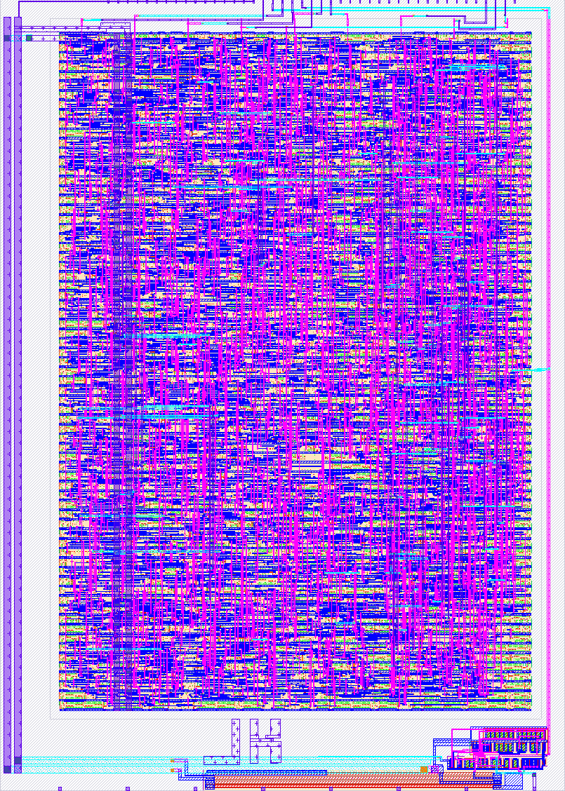
- Author: Jussi Kilpelainen
- Description: S/PDIF (AES3 consumer) receiver converting to an I2S master output, with clock recovery from a single free-running clock
- GitHub repository
- Open in 3D viewer
- Open in Tiny Tapeout Explorer
- Clock: 50000000 Hz
How it works
This project is an S/PDIF (AES3 consumer) receiver that converts an incoming digital-audio stream into an I2S master output. Everything runs from the single free-running Tiny Tapeout clock (50 MHz by default) — there is no external audio clock or PLL. All output timing is regenerated from the clock recovered out of the incoming stream, so the I2S frame rate tracks the source sample rate.
There is also an analog comparator on the chip. It is meant to be used in a configuration where its input is a RC filtered version of the mute output. When mute is disabled, the capacitor is discharged immediately; when enabled, the comparator output follows with a delay. This is a way to implement adjustable, multi-second delays to prevent the amplifier from going on and off between tracks and such.
Signal flow:
spdif_in --> [ spdif_rx ] --L/R samples + recovered UI--> [ i2s_tx ] --> I2S
                  |                                                mute/amp ctrl
              [ mute_detect ]
- spdif_rx — oversamples
spdif_inwith the system clock and measures the inter-transition pulse widths. S/PDIF is biphase-mark coded (BMC): a logic0is one 2T interval, a1is two 1T intervals, and preambles use an illegal 3T interval as a sync marker. The receiver tracks the 1T length, classifies each pulse as short/medium/long, detects the B/M/W sub-frame preambles, re-assembles the 24-bit L/R audio samples, and extracts the block boundary (preamble Z/B). - i2s_tx — regenerates a continuous I2S bit clock (BCLK) and word select (WS/LRCK) from the recovered unit interval and shifts the samples out MSB first with the standard 1-BCLK delay. With a 32-bit slot there are 64 BCLK per frame while an S/PDIF frame spans 128 UI, so BCLK period = 2 x UI. A one-deep double buffer hands samples across; if the recovered rate is not an integer number of clocks, an occasional frame is repeated/skipped (glitch-free, but not bit-exact under that drift).
- mute_detect — asserts
mutewhen there is no valid stream (unlocked) or the audio is digital silence (both channels zero). This is an instantaneous condition: the mute delay and de-bounce/hysteresis between tracks are meant to be added off-chip by an analog comparator on the amplifier. Drive an amplifier standby pin withamp_enable = ~mute. - pwm_audio — a 1-bit PWM DAC of the
(L+R)/2mono downmix. The top 8 bits of the sample set the duty cycle in offset-binary (silence = 50%), with a ~195 kHz carrier at 50 MHz. Low-pass filter the pin to get analog mono audio.
Pinout
| Pin | Dir | Function |
|---|---|---|
ui[0] |
in | spdif_in — S/PDIF serial input |
uo[0] |
out | i2s_bclk — I2S bit clock |
uo[1] |
out | i2s_ws — I2S word select (LRCK; low = left) |
uo[2] |
out | i2s_sd — I2S serial data (MSB first, 1-BCLK delay) |
uo[3] |
out | mute — high when silent / no signal (amp standby) |
uo[4] |
out | locked — decoder synchronised to the stream |
uo[5] |
out | block_start — AES3 channel-status block start (pulse) |
uo[6] |
out | comp_out — analog comparator out |
uo[7] |
out | pwm — mono (L+R)/2 PWM audio (RC low-pass to analog) |
a[0] |
ain | comp_in- analog comparator in |
all uio pins are unused.
Supported sample rates. The receiver needs to oversample the S/PDIF unit interval by roughly 8x or more. At the 50 MHz Tiny Tapeout clock that covers the common consumer rates up to 48 kHz (44.1 kHz = 8.86x, 48 kHz = 8.14x oversampling). 88.2/96 kHz fall below the recommended oversampling at 50 MHz and are not supported on this clock; they would need a faster user clock.
How to test
You need an S/PDIF (AES3 consumer) source: a digital-audio transmitter driving
ui[0], DC-coupled to logic levels (an optical TOSLINK receiver module or a
coax input through a comparator/level shifter both work). Then observe the I2S
bus on uo[0..2] with an I2S-capable DAC or a logic analyser:
- Apply the Tiny Tapeout clock (50 MHz) and pulse
rst_nlow then high. - With no S/PDIF signal,
mute(uo[3]) is high andlocked(uo[4]) is low. - Feed a 32/44.1/48 kHz S/PDIF stream into
ui[0]. Within a few frameslockedgoes high andmutegoes low. uo[0..2]now carry a standard I2S master stream (BCLK, WS, SD) that a DAC can play back.block_start(uo[5]) pulses once per 192-frame AES3 channel-status block.- Remove the signal:
lockeddrops andmutereturns high.
Simulation. A self-checking testbench that drives the wrapped design
through its pins is provided in test/spdif_to_i2s_tb.sv. It contains a
behavioural S/PDIF (BMC) encoder that feeds ui[0] and an I2S decoder that
reconstructs the samples from uo[0..2], then aligns and compares them and
checks locked, mute, block_start and the uo[7] PWM duty. It is the
default test flow (make in test/) and runs under Icarus Verilog:
cd test && make            # or, directly:
iverilog -g2012 -s spdif_to_i2s_tb -o tb.vvp \
    ../src/project.v ../src/spdif_rx.sv ../src/i2s_tx.sv ../src/mute_detect.sv \
    ../src/pwm_audio.sv ../src/spdif_to_i2s.sv spdif_to_i2s_tb.sv
vvp tb.vvp
It prints PASS: 32 consecutive L/R samples decoded correctly on success (and
$fatals otherwise).
External hardware
An S/PDIF source and physical-layer front-end on ui[0]:
- an optical TOSLINK receiver module (e.g. TORX147) driving
ui[0]directly, or - a coax S/PDIF input AC-coupled into a comparator to recover logic levels.
On the output side, either:
- an I2S DAC / audio codec (e.g. PCM5102, MAX98357) wired to
uo[0]= BCLK,uo[1]= LRCK/WS,uo[2]= DATA; or - for a quick mono output, the design should be compatible with an audio Pmod (PWM signal available in uo[7]).
Optionally use mute (uo[3]) for an amplifier standby/enable pin, with the
silence de-bounce done by the integrated analog comparator.
IO
| # | Input | Output | Bidirectional |
|---|---|---|---|
| 0 | spdif_in | i2s_bclk | |
| 1 | i2s_ws | ||
| 2 | i2s_sd | ||
| 3 | mute | ||
| 4 | locked | ||
| 5 | block_start | ||
| 6 | comp_out | ||
| 7 | pwm_audio |
Analog pins
ua | PCB Pin | Internal index | Description |
|---|---|---|---|
| 0 | D | 1 | comp_in |