867 DSLX finite_difference
867 : DSLX finite_difference
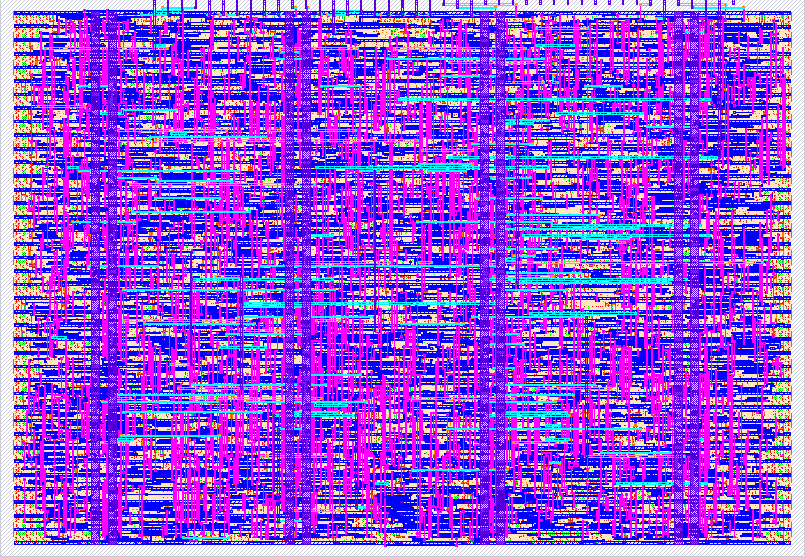
- Author: Leonardo Romor, Henner Zeller
- Description: Cubic polynomial sampler (difference engine) with an SPI request interface and step/dir output, written in DSLX and compiled with google/xls
- GitHub repository
- Open in 3D viewer
- Open in Tiny Tapeout Explorer
- Clock: 10000000 Hz
How it works
The design samples a cubic polynomial with forward differences and outputs the result as step and
direction signals for a stepper motor driver. The source is DSLX. The XLS compiler generates the
Verilog. Only wrapper.sv is hand written.
Four signed 12-bit registers r0, r1, r2 and r3 hold the differences of the polynomial.
Each sample runs three additions: r1 += r0, r2 += r1, r3 += r2. After the additions, r3 is
the new value. No multiplier is needed. To sample p(x) = c0 + c1 x + c2 x^2 + c3 x^3 at
x = 1, 2, 3, ..., load r0 = 6 c3, r1 = 2 c2 - 6 c3, r2 = c1 - c2 + c3 and r3 = c0.
A request has 64 bits. It holds the four registers and a 16-bit sample count. The first bit sent is bit 63.
| Bits | Content |
|---|---|
| 63-52 | r0 |
| 51-40 | r1 |
| 39-28 | r2 |
| 27-16 | r3 |
| 15-0 | sample count |
The core makes one sample for each rising edge of POLY_CLK. After the last sample of the request,
the core waits for the next request. You can send the next request at any time. The core accepts it
when the current request is complete.
The outputs:
STEPis bit 10 of the value. It changes each time the value crosses a multiple of 1024. A driver that steps on the rising edge makes one step for each 2048 units of travel.DIRis the sign ofr2at the timeSTEPrises. 0 means the value increases. 1 means the value decreases.DIRchanges only whenSTEPrises.- When
STEPrises andDIRchanges at the same sample, the core holdsSTEPlow for 128 more clocks. This gives the driver 128 clocks of setup time onDIR. At 10 MHz this is 12.8 us.
The value must not change by more than 1024 in one sample. The value must stay between -2048 and
2047. If the value moves faster, STEP misses crossings. If the value leaves the range, it wraps.
Protocol
SPI input: mode 0. Set SPI_CS_N low and keep it low for two or more system clocks before the
first clock edge. Each rising edge of SPI_SCLK shifts one bit from SPI_MOSI into the request.
Send bit 63 first. Send exactly 64 bits. SPI_CS_N does not reset the bit counter. If you stop a
transfer early, send the missing bits before the next request. The system clock samples the
inputs. Keep SPI_SCLK below one tenth of the system clock. SPI_MISO is always 0.
Sample clock: each rising edge of POLY_CLK makes one sample. Keep the high phase and the low
phase at four or more system clocks each. There is no maximum period. After the last sample of a
request, the core ignores POLY_CLK until the next request arrives.
Output timing: the core updates STEP and DIR on the system clock that makes the sample. DIR
does not change on a falling edge of STEP. STEP keeps its level for one or more full samples.
How to test
You need an SPI master and one output pin for POLY_CLK. A BeagleBone or a Raspberry Pi can
drive the pins from software.
- Set
SPI_CS_Nlow. - Send the 64-bit request on
SPI_MOSI, bit 63 first, one bit for each rising edge ofSPI_SCLK. - Set
SPI_CS_Nhigh. - Pulse
POLY_CLKonce for each sample. - Read
STEPandDIR, or connect them to a step/dir driver.
Example: send r0 = 0, r1 = -30, r2 = 420, r3 = -1800 and count 26. The value rises from
-1410 to 930 and then falls to -1410. After reset, STEP rises after tick 2, falls after tick 5,
rises after tick 21 and falls after tick 24. DIR changes to 1 at tick 21, 128 clocks before
STEP rises.
To move a motor over a long path, send many short requests with r3 = 0. Each request adds its
own steps to the motor position.
The same sources build for the Arty A7-35 board (fpga/xc7/). Pmod JA carries the SPI pins.
Pmod JB carries POLY_CLK, STEP and DIR.
External hardware
An SPI master with one spare output pin for POLY_CLK. A step/dir stepper driver on STEP and
DIR is optional. TMC2209, A4988 and DRV8825 drivers accept the timing above.
IO
| # | Input | Output | Bidirectional |
|---|---|---|---|
| 0 | SPI_SCLK | SPI_MISO (unused, 0) | |
| 1 | SPI_CS_N | STEP | |
| 2 | SPI_MOSI | DIR | |
| 3 | POLY_CLK | ||
| 4 | |||
| 5 | |||
| 6 | |||
| 7 |