519 BPSK Baseband Modulator
519 : BPSK Baseband Modulator
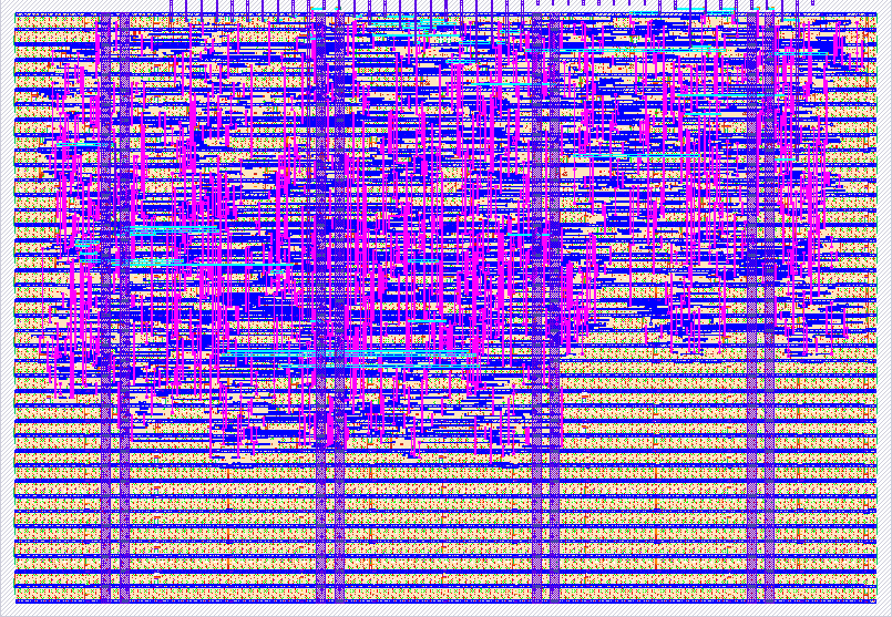
- Author: Siraj Muhammad
- Description: Transmit-only BPSK baseband modulator: PRBS-7 source, +/-1 symbol mapper and polyphase RRC pulse shaper on an 8-bit signed sample bus
- GitHub repository
- Open in 3D viewer
- Open in Tiny Tapeout Explorer
- Clock: 10000000 Hz
How it works
A transmit-only BPSK baseband modulator. The datapath is:
PRBS-7 -> +/-1 BPSK mapper -> polyphase RRC pulse shaper -> 8-bit signed sample bus
-
PRBS-7 generator —
x^7 + x^6 + 1, seed7'h7F, giving a 127-bit period that is short enough to verify by eye in a waveform.prbs_reload(ui[3]) reseeds it. -
BPSK mapper — maps each data bit to a
+/-1symbol.data_sel(ui[1]) chooses between the internal PRBS and an external bit onext_data(ui[2]). -
RRC pulse shaper — root-raised-cosine, rolloff 0.35, 6 symbol span, 25 taps, 8-bit signed coefficients, at 4 samples per symbol.
The shaper is implemented as a polyphase filter rather than a literal 25-tap FIR. Because the mapper emits impulses at 4x with zeros between them, only about 7 taps see a nonzero input at any output phase. The design therefore keeps a 7-deep shift register of symbol signs and selects one of 4 coefficient sets by phase, so each output sample is a 6- or 7-term add/subtract. Since BPSK symbols are
+/-1, every tap is a sign-selected add and no multipliers are needed.The coefficients are scaled so that the worst case — all signs in the fullest branch aligned — sums to
<= 127. Overflow is therefore impossible by construction and there is no saturation logic, which removes the most likely source of disagreement between the RTL and the reference model.
Output is 8-bit signed two's complement on uo[7:0], with sample_valid (uio[0])
pulsing one clock per sample and symbol_tick (uio[1]) one clock per symbol. The raw
PRBS bit is echoed on uio[2] so a host can align for BER measurement. clk_div_sel
(ui[7:4]) divides the input clock to set the symbol rate.
The chip does baseband only. Demodulation, RF upconversion, and BER counting all live off-chip.
How to test
Drive clk and release rst_n, then set tx_enable (ui[0]) high with data_sel
(ui[1]) low to select the internal PRBS-7 source. Shaped samples appear on uo[7:0],
one per sample_valid (uio[0]) pulse, as 8-bit signed two's complement values.
Discard the first 24 samples (6 symbols) after each time tx_enable goes high. The
shaper holds a 7-deep shift register of symbol signs, which is not cleared when
tx_enable is deasserted, so those first samples still contain symbols from before
the enable. From the seventh symbol onward the register holds only new data.
Capture the sample bus on each sample_valid and compare against the Python
reference model, which generates the RRC taps, the PRBS-7 sequence, and the expected
shaped output. Verification is a bit-exact match against that model, run under cocotb
(cd test && make) at both RTL and gate level.
To drive external data instead of the PRBS, set data_sel (ui[1]) high and present the
bit stream on ext_data (ui[2]), advancing one bit per symbol_tick (uio[1]).
Pulsing prbs_reload (ui[3]) reseeds the generator to 7'h7F so a capture can be
aligned to a known starting state.
External hardware
None required to exercise the design — it can be clocked and read directly from the demo board.
For the full transmit chain:
- RP2040 demo board — PIO burst capture of the parallel sample bus, dumped over
USB-CDC as a
.binfile. - GNU Radio on the host — File Source -> Char To Float -> Multiply Const -> Float To Complex, feeding a bladeRF sink.
- bladeRF — RF upconversion. All demodulation (matched filter, timing recovery, slicer, BER counting) is done in GNU Radio on the host.
IO
| # | Input | Output | Bidirectional |
|---|---|---|---|
| 0 | tx_enable | sample[0] (LSB) | sample_valid |
| 1 | data_sel (0=PRBS, 1=ext_data) | sample[1] | symbol_tick |
| 2 | ext_data | sample[2] | prbs_bit |
| 3 | prbs_reload | sample[3] | |
| 4 | clk_div_sel[0] | sample[4] | |
| 5 | clk_div_sel[1] | sample[5] | |
| 6 | clk_div_sel[2] | sample[6] | |
| 7 | clk_div_sel[3] | sample[7] (sign) |