513 6x6 UART Bussbar Switch
513 : 6x6 UART Bussbar Switch
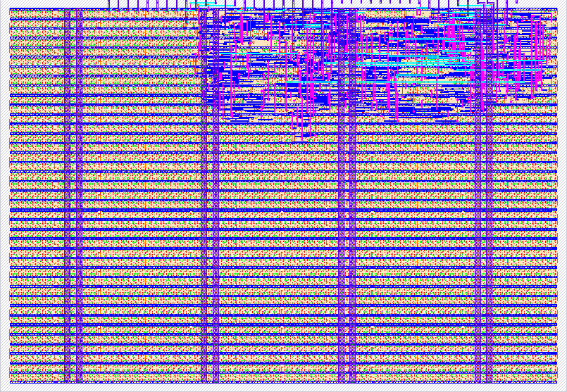
- Author: Asaad Kaadan
- Description: Bidirectional Bussbar Switch for 6 UART Ports
- GitHub repository
- Open in 3D viewer
- Open in Tiny Tapeout Explorer
- Clock: 50000000 Hz
How it works
This project is a bidirectional 6x6 switch bar that connects 6 input ports to 6 output ports. A single input port can be connected to one or multiple output ports. A single output port, on the other hand, can connect only to a single input at any given time.
Port selection is controlled through a serial data-in interface (IN[6]) and a latch (IN[7]). You send 18 bits into the shift register to control 6 output ports: 3 bits for each port. Once the 18 bits have been shifted, a latch signal (active high) activates output configuration. A rst_n (active low) can be used to reset the configuration.
Configuration Bits:
- Bits [2:0] -> Control first output (P1TX)
- Bits [5:3] -> Control second output (P2TX)
- Bits [8:6] -> Control third output (P3TX)
- Bits [11:9] -> Control fourth output (P4TX)
- Bits [14:12] -> Control fifth output (P5TX)
- Bits [17:15] -> Control sixth output (P6TX)
Output Port Selection:
- 000 -> Px TX connects to P1 RX
- 001 -> Px TX connects to P2 RX
- 010 -> Px TX connects to P3 RX
- 011 -> Px TX connects to P4 RX
- 100 -> Px TX connects to P5 RX
- 101 -> Px TX connects to P6 RX
- 110 -> Px TX is disconnected
- 111 -> Px TX is disconnected
Pinout
Inputs
- ui[0]: "P1 RX"
- ui[1]: "P2 RX"
- ui[2]: "P3 RX"
- ui[3]: "P4 RX"
- ui[4]: "P5 RX"
- ui[5]: "P6 RX"
- ui[6]: "Configuration serial data in"
- ui[7]: "Configuration latch"
Outputs
- uo[0]: "P1 TX"
- uo[1]: "P2 TX"
- uo[2]: "P3 TX"
- uo[3]: "P4 TX"
- uo[4]: "P5 TX"
- uo[5]: "P6 TX"
- uo[6]: ""
- uo[7]: ""
UART Forwarder
This switch can be used to connect six UART ports as well where each port has two pins (TXD, RXD). This sketch, for example, shows:
- Port P1 is connected to port P4 and P4 is connected to P1 so it's bidirectional forwarding
- Port P2 is connected to ports P5 and P6 but only in one direction
- Port P3 is connected to itself (loopback)
This can be translated to the following configurations:
- P1 TX > P4 RX
- P2 TX is disconnected
- P3 TX > P3 RX
- P4 TX > P1 RX
- P5 TX > P2 RX
- P6 TX > P2 RX
Configuration bits (it's binary stream without whitespace): 001 001 000 010 111 011
<img width="427" height="446" alt="switch2" src="https://github.com/user-attachments/assets/0fcd3fde-5e9c-4450-811a-0fd448f4df9b" />
How to test
Use an external microcontroller to provide configuration stream.
test_data = 18'b001_001_001_001_001_001;
shift_word(test_data);
latch_outputs();
External hardware
No external hardware is required. Just connect any serial UART interface to TXD, RXD pins.
IO
| # | Input | Output | Bidirectional |
|---|---|---|---|
| 0 | P1 RXD | P1 TXD | |
| 1 | P2 RXD | P2 TXD | |
| 2 | P3 RXD | P3 TXD | |
| 3 | P4 RXD | P4 TXD | |
| 4 | P5 RXD | P5 TXD | |
| 5 | P6 RXD | P6 TXD | |
| 6 | Configuration serial data in | ||
| 7 | Configuration latch |