142 Adaptive-Precision FFT
142 : Adaptive-Precision FFT
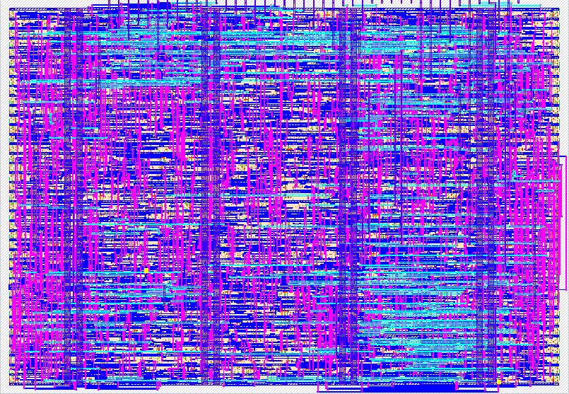
- Author: Aditya R Prasad, Suddep P Hande, Shylashree N, RV College of Engineering
- Description: An Error-Budget-Driven Adaptive-Precision Architecture for Efficient FFT Processing
- GitHub repository
- Open in 3D viewer
- Open in Tiny Tapeout Explorer
- Clock: 100000000 Hz
Credits
We gratefully acknowledge the Center of Excellence (CoE) in Integrated Circuits and Systems (ICAS) and the Department of Electronics and Communication Engineering (ECE) for providing the necessary resources and guidance. Special thanks to Dr. H V Ravish Aradhya (HoD- ECE), Dr. K R Usha Rani (Associate Dean-PG), Dr. K. S. Geetha (Vice Principal) and Dr. K. N. Subramanya (Principal) for their constant encouragement and support in facilitating this Tiny Tapeout SKY26C submission.
How it works
This project implements a hardware-efficient adaptive-precision radix-2 FFT butterfly processing element.
The design accepts two complex 8-bit input values through an 8-bit multiplexed input interface. The four input bytes are supplied sequentially as:
- X_re - real part of X
- X_im - imaginary part of X
- Y_re - real part of Y
- Y_im - imaginary part of Y
The butterfly performs a complex radix-2 butterfly operation using the twiddle-factor representation implemented in the RTL datapath. The arithmetic supports three selectable precision modes: 4-bit, 6-bit, and 8-bit.
The precision is selected automatically using two hardware-friendly indicators:
- a sensitivity estimate based on the magnitude of the current input operands
- an estimated quantization-error measure compared against a 2-bit programmable error budget
The controller first attempts to use the lowest precision. If the estimated error is within the allowable budget, 4-bit precision is selected. If the estimated error exceeds the allowable limit, the controller escalates to 6-bit precision. If the error constraint is still not satisfied, 8-bit precision is selected.
The precision-selection policy therefore attempts to use the minimum precision that satisfies the estimated error constraint.
The multiplier is time-multiplexed and reused across multiple clock cycles instead of using multiple parallel multipliers. A small finite-state machine (FSM) controls input capture, precision selection, multiplication, result calculation, and output sequencing.
The output is also multiplexed over the 8-bit output interface. The four output bytes are provided sequentially as:
- Z0_re - real part of the first butterfly output
- Z0_im - imaginary part of the first butterfly output
- Z1_re - real part of the second butterfly output
- Z1_im - imaginary part of the second butterfly output
The bidirectional interface is used for control and status signals. The pins are allocated as follows:
- uio[7:6] - 2-bit error-budget input
- uio[5] - START input
- uio[4] - BUSY status output
- uio[3] - VALID status output
- uio[2] - precision-escalation status output
- uio[1:0] - selected-precision status output
The selected precision is encoded as:
- 00 - 4-bit
- 01 - 6-bit
- 10 - 8-bit
The design is intended as an adaptive FFT butterfly processing element rather than a complete N-point FFT engine. Multiple instances of the processing element could be used as part of a larger FFT architecture.
How to test
The design is tested using a clocked 8-bit multiplexed interface.
The clock should be supplied at the intended operating frequency. The current RTL verification uses a 10 ns clock period (100 MHz nominal clock).
After reset is released, provide the 2-bit error-budget value on uio[7:6] and generate a START pulse on uio[5].
For each butterfly transaction, provide the four 8-bit input bytes sequentially on ui[7:0]:
- X_re
- X_im
- Y_re
- Y_im
The inputs are signed 8-bit two's-complement values.
After the input transaction has been accepted, monitor the status pins:
- uio[4] = BUSY
- uio[3] = VALID
- uio[2] = precision-escalation indicator
- uio[1:0] = selected precision
The selected precision is encoded as:
- 00 = 4-bit
- 01 = 6-bit
- 10 = 8-bit
When VALID is asserted, read the four result bytes from uo_out[7:0]. The bytes are presented sequentially as:
- Z0_re
- Z0_im
- Z1_re
- Z1_im
The testbench checks both the selected precision and the calculated butterfly outputs.
The RTL testbench includes directed tests for:
- 4-bit precision selection
- 6-bit precision selection
- 8-bit precision selection
- different error-budget settings
- signed positive and negative input values
- different internal twiddle-factor cases
- BUSY and VALID operation
- precision escalation status
- START edge detection
The testbench can be run with a Verilog simulator such as Icarus Verilog using the DUT and tb.v files.
Example simulation commands:
iverilog -g2012 -o simv fft_DUT.v project.v tb.v
vvp simv
A successful simulation should report the individual directed tests as passing and should terminate without a global simulation timeout.
External hardware
No external hardware is required for the FFT butterfly itself.
The design uses only the standard Tiny Tapeout digital interface:
- clock
- reset
- 8-bit input interface
- 8-bit output interface
- 8 bidirectional GPIO pins
The design can be verified through RTL simulation without any external hardware.
For physical silicon testing, the fabricated Tiny Tapeout design can be connected to a suitable Tiny Tapeout-compatible carrier/demo board or other digital test platform capable of providing the clock, reset, input data and control signals and observing the output and status signals.
No external FFT-specific hardware is used.
IO
| # | Input | Output | Bidirectional |
|---|---|---|---|
| 0 | DATA[0] | RESULT[0] | PRECISION[0] |
| 1 | DATA[1] | RESULT[1] | PRECISION[1] |
| 2 | DATA[2] | RESULT[2] | ESCALATED |
| 3 | DATA[3] | RESULT[3] | VALID |
| 4 | DATA[4] | RESULT[4] | BUSY |
| 5 | DATA[5] | RESULT[5] | START |
| 6 | DATA[6] | RESULT[6] | ERROR_BUDGET[0] |
| 7 | DATA[7] | RESULT[7] | ERROR_BUDGET[1] |