174 CPU8
174 : CPU8
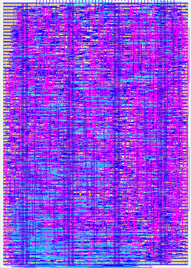
- Author: Aryan
- Description: Small 8-bit accumulator CPU with UART programming, RAM, ALU, branching, and GPIO.
- GitHub repository
- Open in 3D viewer
- Open in Tiny Tapeout Explorer
- Clock: 60000000 Hz
How it works
CPU8 is a small custom 8-bit processor designed for Tiny Tapeout. It uses an 8-bit accumulator-based architecture with a custom instruction set.
The CPU contains:
-
An 8-bit accumulator
-
An instruction memory that can be programmed through UART
-
An 8-bit RAM for data storage
-
An ALU supporting:
- ADD
- SUB
- AND
- OR
- XOR
- NOT
- INC
- DEC
-
Conditional branches:
- Jump
- Branch if zero
- Branch if not zero
-
HALT instruction
-
8-bit GPIO input and output
-
GPIO output-enable control
-
UART programming interface
Each instruction is 8 bits wide. The upper 4 bits select the instruction, while the lower 4 bits provide an immediate value, memory address, or branch/jump target.
Programs are uploaded through the UART interface. A programming command writes instructions into instruction memory, while a start command resets the CPU's program counter and begins execution from address 0.
The CPU uses memory-mapped I/O for GPIO:
0xC— GPIO output0xD— GPIO output enable/direction0xE— GPIO input
The remaining RAM addresses are available for normal data storage.
How to test
The CPU can be tested by connecting a UART interface to the programming input and sending 8-bit UART data using an 8-N-1 configuration.
The programming protocol is:
- Send
0xAAto begin an instruction write. - Send the 8-bit instruction address.
- Send the 8-bit instruction data.
- Repeat for every instruction in the program.
- Send
0x55to start the CPU.
The CPU begins execution at program counter 0 after receiving the start command.
For simulation, the included Cocotb testbench programs the CPU through the same UART interface and verifies the GPIO output. The testbench checks reset, enable, UART programming, arithmetic and logic instructions, RAM store/load, GPIO input/output, jumps, conditional branches, HALT, reset recovery, and multiple UART writes.
A successful test should produce PASS messages for all CPU functionality tests.
External hardware
No external hardware is required for basic operation.
The CPU uses the Tiny Tapeout GPIO pins for:
- 8-bit GPIO input
- 8-bit GPIO output
- GPIO output-enable signals
A UART interface can be connected to the UART input used for programming the instruction memory.
For physical testing, an external USB-to-UART adapter or microcontroller can be used to send the programming commands and instruction bytes to the CPU.
IO
| # | Input | Output | Bidirectional |
|---|---|---|---|
| 0 | GPIO_IN_0 | GPIO_OUT_0 | UART_RX |
| 1 | GPIO_IN_1 | GPIO_OUT_1 | GPIO_OE_0 |
| 2 | GPIO_IN_2 | GPIO_OUT_2 | GPIO_OE_1 |
| 3 | GPIO_IN_3 | GPIO_OUT_3 | GPIO_OE_2 |
| 4 | GPIO_IN_4 | GPIO_OUT_4 | GPIO_OE_3 |
| 5 | GPIO_IN_5 | GPIO_OUT_5 | GPIO_OE_4 |
| 6 | GPIO_IN_6 | GPIO_OUT_6 | GPIO_OE_5 |
| 7 | GPIO_IN_7 | GPIO_OUT_7 | GPIO_OE_6 |