841 FP8 (E4M3) Floating-Point Unit
841 : FP8 (E4M3) Floating-Point Unit
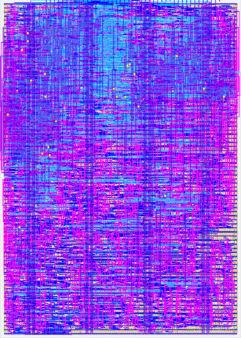
- Author: Raphael Lopes Pinheiro
- Description: 8-bit IEEE FP8 E4M3 FPU, 18 ops: add/sub/mul/div/sqrt (iterative variable-latency div & sqrt) + min/max/abs/neg/copysign/classify/compare/scalb/roundToIntegral + int8/uint8 conversions (RISC-V FCVT saturating semantics). Streaming valid/ready I/O, pipelined, multiple ops in flight. Exhaustively verified: all 1,843,968 input combinations at RTL and gate level.
- GitHub repository
- Open in 3D viewer
- Open in Tiny Tapeout Explorer
- Clock: 10000000 Hz
How it works
This project tapes out an 8-bit floating-point unit (FPU) in the FP8 E4M3
format: 1 sign bit, 4 exponent bits (bias 7) and 3 mantissa bits. The core,
tiny_fp8_unit, is a pipelined, elastic datapath that implements a
18-operation IEEE-754-style instruction set (opcodes 0–17):
- Arithmetic: add, subtract, multiply, divide, square-root. Divide and sqrt share one iterative, variable-latency unit (1 digit/cycle); everything else is single-cycle in the pipeline.
- Comparison / selection: min, max, compare, classify (IEEE-2019 semantics, NaN-aware).
- Manipulation: absolute value, negate, copy-sign, scale-by-power-of-two (scalb), round-to-integral.
- Integer conversion: fp8↔int8 and fp8↔uint8 (opcodes 14–17), with RISC-V
FCVTsemantics — round by the current mode first, then range-check and saturate, raisinginvalidon out-of-range and NaN. This is what lets a host CPU move operands in and out of the unit without software fix-up.
Five IEEE rounding modes (nearest-even, toward-zero, up, down, nearest-odd) and full classification + exception flags are produced with every result.
Verification: the design is signed off exhaustively — all 1,843,968
possible (operand, opcode, rounding-mode) combinations are replayed against a
Fraction-exact reference model, at RTL and against the post-place-and-route
netlist. Nothing is sampled. Exhaustive sign-off is impossible in wider
floating-point formats and is one of the practical advantages of a minifloat.
The core's native interface is far wider than Tiny Tapeout's pin budget (~32 in,
~28 out). To fit, the top-level wrapper tt_um_fp8_fpu time-multiplexes
everything onto a single 8-bit data bus and exposes the core as a byte stream
with two independent valid/ready handshakes — one for input, one for
output. Because the handshakes are independent, the host keeps feeding new
operands while draining previous results, so several operations stay in flight.
Operation
input  bytes per op :  A -> B -> CTRL       (B and/or CTRL may be skipped, see sticky)
output bytes per op :  RESULT [ -> FLAGS -> EXCEPTIONS ]   (last two only if READ_FULL)
CTRLbyte ={ rm = ui_in[7:5], opcode = ui_in[4:0] }.- FP8 E4M3 encoding: bit 7 = sign, bits 6:3 = exponent (bias 7), bits 2:0 =
mantissa. E.g.
1.0 = 0x38,2.0 = 0x40.
A transfer happens on the rising clk edge where both valid and ready
are high; results come out in the same order the operations went in. Two
"sticky" bits let the host skip unchanged fields — STICKY_B reuses the last B,
STICKY_CTRL reuses the last {rm, opcode} — and READ_FULL selects 1 byte/op
(result only) or 3 bytes/op (result + flags + exceptions). The uio pins carry
the handshake: IN_VALID/IN_READY (input), OUT_VALID/OUT_READY (output),
the three config bits, and FPU_BUSY. uio_oe = 8'b1000_0110.
How to test
After reset the bus is idle. To compute A op B in the simplest "full" mode
(STICKY_* low, READ_FULL = 1):
- Drive
Aonui_in, assertIN_VALID, and wait for the cycle whereIN_READYis also high — that byte is now accepted. - Repeat for
B, then theCTRLbyte{rm, opcode}. TheCTRLbyte issues the operation. - Assert
OUT_READYand readuo_outon each cycle whereOUT_VALIDis high: first the result, then flags, then exceptions.
Example — 1.0 + 1.0: send 0x38 (A), 0x38 (B), 0x00 (CTRL: rm=0, op=ADD);
read 0x40 (= 2.0). The cocotb suite in test/ drives the pins exactly like a
silicon host and self-checks every result/flag/exception against the golden
reference, including a back-pressure stress test and a sticky-mode test.
External hardware
None required. Any host that can drive the 8 data inputs and the handshake pins
and read the 8 data outputs — a microcontroller (the demo board's RP2040, an
ESP32/STM32, …), an FPGA, or a logic analyser with a pattern generator — can
operate the FPU. Because the host also supplies clk, it controls the timing and
can single-step the interface.
IO
| # | Input | Output | Bidirectional |
|---|---|---|---|
| 0 | DATA_IN[0] (operand / control byte) | DATA_OUT[0] (result / flags / exceptions) | IN_VALID (input: host has a DATA_IN byte) |
| 1 | DATA_IN[1] | DATA_OUT[1] | IN_READY (output: core can accept a byte) |
| 2 | DATA_IN[2] | DATA_OUT[2] | OUT_VALID (output: DATA_OUT byte is valid) |
| 3 | DATA_IN[3] | DATA_OUT[3] | OUT_READY (input: host consumed DATA_OUT byte) |
| 4 | DATA_IN[4] | DATA_OUT[4] | STICKY_CTRL (input: reuse last rm/opcode) |
| 5 | DATA_IN[5] | DATA_OUT[5] | STICKY_B (input: reuse last B operand) |
| 6 | DATA_IN[6] | DATA_OUT[6] | READ_FULL (input: output result+flags+exc) |
| 7 | DATA_IN[7] | DATA_OUT[7] | FPU_BUSY (output) |