682 Systolic Processing Element
682 : Systolic Processing Element
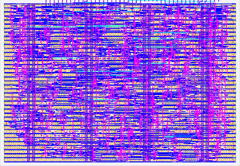
- Author: Hayden Evans
- Description: A weight-stationary processing element (PE) implementing the core compute primitive of a systolic array neural network accelerator.
- GitHub repository
- Open in 3D viewer
- Open in Tiny Tapeout Explorer
- Clock: 10000000 Hz
Systolic Processing Element
Overview
This project is a weight-stationary processing element (PE) implementing the core compute primitive of a systolic array neural network accelerator. The design features a 3-stage pipeline: int8 multiply-accumulate, bias addition, and Leaky ReLU activation (β=0.25).
How it works
Interface
The chip communicates through a time-multiplexed 8-bit data bus (ui_in) and a 4-bit control input (uio[0:3]). Three control signals govern data loading: asserting load_weight (uio[0]) captures the value on ui_in into the weight register; asserting load_bias (uio[1]) captures it into the bias register; asserting accumulate (uio[2]) treats ui_in as an activation value and begins computation. A fourth control signal reset_acc (uio[3]) clears the accumulator between independent computations. Two status signals are output: output_valid (uio[4]) goes high exactly 3 clock cycles after an accumulate pulse, indicating the result on uo_out is ready to read; overflow (uio[5]) indicates the output was saturated (clamped) to the int8 range.
This design is implemented in a 3-stage pipeline as follows:
Stage 1: Multiply-Accumulate
On each accumulate pulse, the chip multiplies the stationary weight register (int8) by the incoming activation (int8 on ui_in), producing a 16-bit signed product. This product is added to the 16-bit accumulator. The accumulator persists between accumulate pulses, enabling dot products to be accumulated across multiple clock cycles — a 128-input neuron requires 128 accumulate cycles. The accumulator is saturated to int16 range (−32,768 to +32,767) using a 17-bit intermediate sum for overflow detection. The result is latched into the Stage 1 output register on the clock edge.
Stage 2: Bias Addition
One cycle after Stage 1, the accumulated MAC result is added to the bias register (int8, sign-extended to 17 bits). The result is saturated to int16 range. Bias allows neurons to activate independently of the dot product magnitude, shifting the activation function threshold. This stage is pipelined separately from Stage 1 to keep each stage's critical combinational path short and allow higher clock frequencies.
Stage 3: Leaky ReLU Activation and int8 Saturation
One cycle after Stage 2, the activation function is applied. The sign bit of the 16-bit biased result is tested: if positive, the value passes through unchanged; if negative, it is arithmetically right-shifted by 2 positions (dividing by 4, equivalent to multiplying by β=0.25). This is Leaky ReLU with β=0.25, implemented using only wiring — zero additional gates, accomplished by arithmetic shift. The result is then saturated to int8 range (−128 to +127) before appearing on uo_out. The overflow flag records whether saturation occurred.
Bit-Width Progression
Input: 8-bit signed (int8) — weights, biases, activations Stage 1 Accumulator: 16-bit signed (int16) — MAC running sum Stage 2 Bias: 16-bit signed (int16) — MAC + bias Stage 3 Output: 8-bit signed (int8) — final result
How to test
- Assert load_weight, drive weight on ui_in → clock one edge → release
- Assert load_bias, drive bias on ui_in → clock one edge → release
- Assert reset_acc → clock one edge → release
- Assert accumulate, drive activation on ui_in → clock one edge → release
- Wait 3 clock cycles
- Read uo_out when output_valid (uio[4]) is HIGH Repeat from step 3 for each new computation. Repeat from step 1 only when weight or bias changes.
External hardware
Terasic MAX10 DE10-Lite was used in prototyping and testing this design will also be used for further testing.
IO
| # | Input | Output | Bidirectional |
|---|---|---|---|
| 0 | shared data bus[0] | output[0] | load_weight (input) |
| 1 | shared data bus[1] | output[1] | load_bias (input) |
| 2 | shared data bus[2] | output[2] | accumulate (input) |
| 3 | shared data bus[3] | output[3] | reset_acc (input) |
| 4 | shared data bus[4] | output[4] | output_valid (output) |
| 5 | shared data bus[5] | output[5] | overflow_out |
| 6 | shared data bus[6] | output[6] | |
| 7 | shared data bus[7] | output[7] |