704 Kalman Filter Hardware Accelerator
704 : Kalman Filter Hardware Accelerator
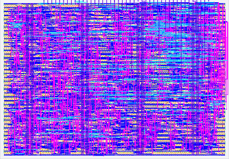
- Author: Jose Ramirez
- Description: A hardware accelerator for the measurement update in the basic kalman filter algorithm
- GitHub repository
- Open in 3D viewer
- Open in Tiny Tapeout Explorer
- Clock: 50000000 Hz
How it works
This project implements the Kalman filter measurement-update ("correct") step as a fixed-function hardware accelerator targeting a 1×1 Tiny Tapeout tile (sky130 HD standard-cell library).
Fixed-point number format
All values use 10-bit signed Q4.6 fixed-point:
| Property | Value |
|---|---|
| Width | 10 bits (signed two's complement) |
| Scale factor | 64 (divide integer value by 64 to get the real number) |
| Range | −8.0 to +7.984375 |
| Resolution | 1/64 ≈ 0.015625 |
To encode a real value: Q46_value = round(real_value × 64). For example, 1.5 → 0x0060 (96), 5.0 → 0x0140 (320).
Registers are 10 bits wide but transferred as two bytes:
- MSB byte (byte_sel = 0): bits [9:8] in the low two bits of the data byte (bits [7:2] are ignored on write, zero-padded on read)
- LSB byte (byte_sel = 1): bits [7:0]
Algorithm (1D scalar Kalman update, H = 1)
The design handles a scalar state (single position variable). The time-update (predict) step runs in host software; only the measurement-update is accelerated.
y_tilde = z − x_in               (innovation)
S       = P_in + R                (innovation covariance)
S_inv   = floor(4096 / S)         (reciprocal via restoring divider; S_inv/64 ≈ 1/S)
K       = (P_in × S_inv) >> 6    (Kalman gain, Q4.6 multiply)
ky      = (K × y_tilde)   >> 6   (K × innovation, Q4.6 multiply)
x_out   = x_in + ky              (corrected state)
kp      = (K × P_in)      >> 6   (K × P, Q4.6 multiply)
P_out   = P_in − kp              (updated covariance)
Architecture
The top module (tt_um_joram200, top.sv) instantiates two sub-modules:
par_reg (interface.sv) — Parallel GPIO register file
Provides a byte-serial read/write interface over the GPIO pins. Write enable and start inputs pass through two-stage synchronizer flip-flops before use, preventing metastability. The done_latch output bit in STAT stays high after a computation completes until the next start.
kalman_update (compute_core.sv) — 8-state Kalman FSM
Contains one shared multiplier and one divider, sequenced by an 8-state FSM:
| State | Operation | Duration |
|---|---|---|
| IDLE | Wait for start | — |
| S_COMP | S = P_in + R (combinational) | 1 cycle |
| DIV | S_inv = floor(4096 / S) | 14 cycles |
| K_COMP | K = P_in × S_inv >> 6 | 11 cycles |
| KY_COMP | ky = K × y_tilde >> 6 | 11 cycles |
| X_ADD | x_out = x_in + ky (combinational) | 1 cycle |
| P_UPDATE | kp = K × P_in >> 6; P_out = P_in − kp | 11 cycles |
| DONE_S | Assert done for one cycle | 1 cycle |
Total latency per measurement update: ~50 clock cycles (~1 µs at 50 MHz).
int10_mul_seq — Signed 10×10 → 10 shift-and-add multiplier (Baugh-Wooley algorithm), 11 cycles. Computes (a × b) >> 6 to stay in Q4.6.
int10_div — 14-cycle restoring divider computing floor(4096 / S_Q46). Saturates the output to 0x1FF (511) when S ≤ 8 (Q4.6) to prevent overflow.
How to test
Write protocol (byte-serial, MSB first)
To write a 10-bit value to a register:
- Place register address on
uio[2:0],0onuio[3](BYTE_SEL = MSB), and the MSB byte onui[7:0]. Only bits [1:0] of the data byte are used (they become register bits [9:8]). - Pulse
uio[4](WR_EN) high for at least 1 clock cycle, then low. The write fires on the rising edge detected after 2-FF synchronization. - Place
1onuio[3](BYTE_SEL = LSB) and the LSB byte onui[7:0]. - Pulse
uio[4](WR_EN) high then low again. The 10-bit write is now complete.
Read protocol (combinational)
Place the register address on uio[2:0] and the desired byte on uio[3] (0 = MSB, 1 = LSB). uo[7:0] drives the selected byte immediately (combinational — no clock edge needed).
Per-update procedure
- Write inputs to registers 2, 3, 5 (and optionally 7 to change R) using the write protocol above.
- Pulse
uio[6](START) high for at least 1 clock cycle, then low. The FSM begins on the rising edge. - Poll register 1 (STAT): read
uo_outwithuio[2:0]=3'b001,uio[3]=1(LSB byte). Bit [0] of the result isdone_latch; wait until it is 1. - Read x_out from register 4 (MSB then LSB byte). Read P_out from register 6.
- Feed x_out and P_out as x_in and P_in for the next iteration (after the software time-update step).
Worked example
Inputs: z = 1.5 (0x0060), x_in = 0.0 (0x0000), P_in = 1.0 (0x0040), R = 5.0 (default 0x0140)
y_tilde = 96 − 0    = 96          (1.5 − 0.0 = 1.5)
S       = 64 + 320  = 384         (1.0 + 5.0 = 6.0)
S_inv   = floor(4096 / 384) = 10  (0.166... in Q4.6 ≈ 0.15625)
K       = (64 × 10) >> 6  = 10    (0.15625 in Q4.6)
ky      = (10 × 96) >> 6  = 15    (0.234375 in Q4.6)
x_out   = 0 + 15    = 15          (0.234375)
kp      = (10 × 64) >> 6  = 10    (0.15625 in Q4.6)
P_out   = 64 − 10   = 54          (0.84375)
Expected register reads: x_out = 0x000F, P_out = 0x0036. The CI testbench verifies this with a ≤ 4 ULP tolerance.
Software reset
Assert uio[5] (SW_RST) high to reset the Kalman core at any time without a full chip reset. The FSM returns to IDLE on the next clock edge. Deassert before issuing a new start.
Simulation
The cocotb testbench (test/test.py) runs the above scenario at 50 MHz, polling STAT until done, then reading x_out and P_out and verifying within 4 ULP of the integer Q4.6 reference model.
External hardware
None. The accelerator requires only clock, reset, and the standard Tiny Tapeout GPIO pins. No external components or peripherals are needed.
IO
| # | Input | Output | Bidirectional |
|---|---|---|---|
| 0 | WR_DATA[0] | RD_DATA[0] | ADDR[0] (register address bit 0) |
| 1 | WR_DATA[1] | RD_DATA[1] | ADDR[1] (register address bit 1) |
| 2 | WR_DATA[2] | RD_DATA[2] | ADDR[2] (register address bit 2) |
| 3 | WR_DATA[3] | RD_DATA[3] | BYTE_SEL (0=MSB byte, 1=LSB byte) |
| 4 | WR_DATA[4] | RD_DATA[4] | WR_EN (write enable, rising-edge triggered) |
| 5 | WR_DATA[5] | RD_DATA[5] | SW_RST (software reset, active high level) |
| 6 | WR_DATA[6] | RD_DATA[6] | START (start trigger, rising-edge one-shot) |
| 7 | WR_DATA[7] | RD_DATA[7] |