480 SIMON V2
480 : SIMON V2
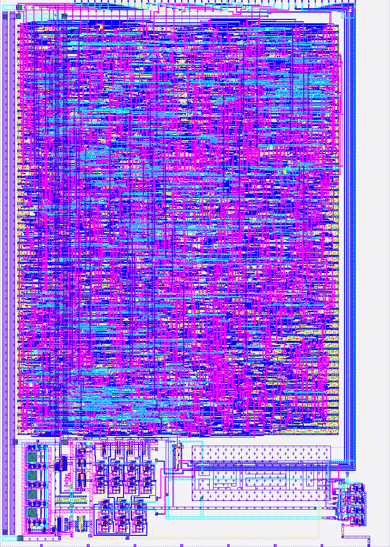
- Author: Libor Miller
- Description: Cryptographic accelerator with SPI interface V2
- GitHub repository
- Open in 3D viewer
- Open in Tiny Tapeout Explorer
- Clock: 50000000 Hz
How it works
Hardware implementation of the Simon block cipher (32/64 configuration) integrated with an SPI Slave interface. The design allows a Master device to write a 64-bit key and 32-bit data block, configure the operation mode (Encrypt/Decrypt), and read back the result. This 2nd version also contains variable frequency oscillator and measurment output.
SPI Interface
SPI Mode 3 (CPOL=1, CPHA=1), MSB first. SPI SCK frequency must be at most CLK/8 for reliable operation.
Pin Mapping
| Pin | Signal | Direction | Description |
|---|---|---|---|
| uio[0] | CS_n | input | Chip select, active low |
| uio[1] | MOSI | input | Master out, slave in |
| uio[2] | MISO | output | Master in, slave out |
| uio[3] | SCK | input | SPI clock from master |
SPI Command Protocol
First byte of each CS frame selects the command:
| Command | Code | Data | Description |
|---|---|---|---|
| Write Key | 0x01 | + 8 data bytes, LSB first | Load 64-bit encryption key |
| Write Block | 0x02 | + 4 data bytes, LSB first | Load 32-bit data block |
| Encrypt | 0x03 | none | Start encryption |
| Decrypt | 0x04 | none | Start decryption |
| Read Status | 0x05 | + 1 dummy byte | Returns {7'b0, done} on MISO |
| Read Result | 0x06 | + 4 dummy bytes | Returns 32-bit result on MISO, LSB first |
Current starved ring oscillator and measurement output
There is a ring oscillator, its output frequency can be set via 3 bit DAC. There is also an amux which selects which measurement gets to the analog pin.
| Pin | Signal | Description |
|---|---|---|
| ui[0] | DAC[0] | Bit 0 of DAC |
| ui[1] | DAC[1] | Bit 1 of DAC |
| ui[2] | DAC[2] | Bit 2 of DAC |
| ui[3] | AMUX[0] | Select 0 of measurement on analog pin 0 |
| ui[4] | AMUX[1] | Select 0 of measurement on analog pin 0 |
| ui[5] | AMUX_ENABLE | Enables amux which conects line to analog pin 0 |
| ui[6] | CLK_INTERNAL_ENABLE | Switches from ring oscillator to external clock for digital block |
How to test
Testing in local enviroment, you need Podman installed on your system. make gds, make rtl -> create temporary podman enviroment and tests src/digital_source_files/digital_top.v against cocotb test. With manufactured testing can be done via SPI avilable on RP2350B MCU in the devkit (GPIO pins 25-28). Control of the ring oscillator and amux can be done vie GPIO17-GPIO23.
External hardware
Oscilloscope with low cappacitance probes, for measuring the output of analog pin 0.
IO
| # | Input | Output | Bidirectional |
|---|---|---|---|
| 0 | DAC[0] | CS_n | |
| 1 | DAC[1] | MOSI | |
| 2 | DAC[2] | MISO | |
| 3 | AMUX[0] | SCK | |
| 4 | AMUX[1] | ||
| 5 | AMUX_ENABLE | ||
| 6 | CLK_INTERNAL_ENABLE | ||
| 7 |
Analog pins
ua | PCB Pin | Internal index | Description |
|---|---|---|---|
| 0 | C | 0 | AMUX_OUT |