204 All-Digital Supply Droop Detector
204 : All-Digital Supply Droop Detector
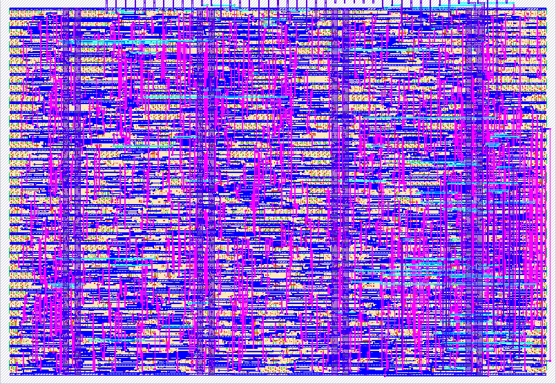
- Author: rcyaon
- Description: Ring-oscillator VDD sensor with on-tile switching aggressor; reports RO period or frequency to watch the tile's own supply sag
- GitHub repository
- Open in 3D viewer
- Open in Tiny Tapeout Explorer
- Clock: 50000000 Hz
How it works
An all-digital supply droop detector. A ring oscillator's frequency is a strong function of its local supply: gate delay scales roughly with $C_L V_{DD} / I_D$, and $I_D$ collapses as $(V_{DD}-V_{th})$ shrinks, so a few percent of droop shows up as a few percent of frequency shift. The tile carries three pieces:
- Sensor (
ro_osc.v,droop_sensor.v): a nand-enabled ring of 25dlygate4sd3cells feeding a 10-stage async ripple divider. One tapped bit (÷16 … ÷1024) crosses into the system clock domain through a 2ff synchronizer; nothing multi-bit ever crosses. - Aggressor (
aggressor.v): 64 flops toggling on the same clock edge, in continuous / single-burst / periodic-burst modes. Every toggle pulls a synchronized slug of dynamic current through the tile's rail: a controlled, repeatable di/dt event. - Measurement: period mode counts clock cycles per divided-RO period (fast sampling: droop ⇒ RO slows ⇒ count rises). Frequency mode counts divided-RO edges in an 8192-clock window (slow, high resolution, for the static transfer curve).
- Self-test source (
uio[2]): a clk/2 square wave that replaces the ring at the input of the divider. Its counts are exact and known, so the divider, synchronizer, both measurement modes and the saturation flag can be checked without trusting the oscillator. It is also what makes the measurement path runnable in gate-level simulation: under the sky130FUNCTIONALcell models every combinational cell is zero-delay, so the hardened ring is a zero-delay loop that stalls an event simulator at a single timestamp.
What this measures is the envelope of the supply excursion at µs-ish timescales set by the divided-RO sample rate (package/board-level sag against the decoupling network), not the ns-scale instantaneous notch.
How to test
- Self-test: set
uio[2]=1and the sensor measures a clk/2 square wave instead of the ring. Period mode then reads 33 counts at tap ÷16 and 129 at ÷64 (the divider periods of a clk/2 source, plus one clock of synchronizer offset), and pins at 0xff withuio[6]raised at ÷256. Wrong numbers here mean the counting path is broken rather than the supply. Clearuio[2]to return to the ring. - Baseline: RO off vs on (
ui[7]), log the divided-RO frequency per tap onuio[5]with a scope or counter. - Static calibration (frequency mode): set
ui[6]=1, power the breakout from a bench supply, sweep VDD and record the sample byte onuo[7:0]versus voltage. This is the sensor's transfer curve; everything after is read through it. - Droop (period mode): set
ui[6]=0, arm periodic bursts (ui[1:0]=11), trigger the scope onuio[4](aggressor active) and capture the sample stream onuo[7:0]with a logic analyzer clocked byuio[3](valid). Sweep burst length onui[5:3]and overlay the captures.
If uio[6] (saturation) goes high, the sample has pinned at 0xff: select a
lower divider tap on uio[1:0].
External hardware
None required for the ASIC. A bench supply plus a scope or logic analyzer is
enough; uio[5] (divided RO), uio[4] (aggressor active) and uio[3] (valid)
are the useful probe points.
An optional Tang Nano 20K port of the same RTL lives in fpga/, which streams
samples over the onboard USB-UART at 115200 baud.
IO
| # | Input | Output | Bidirectional |
|---|---|---|---|
| 0 | AGG_MODE0 | SAMPLE0 | TAP_SEL0 |
| 1 | AGG_MODE1 | SAMPLE1 | TAP_SEL1 |
| 2 | AGG_TRIG | SAMPLE2 | ST_SEL |
| 3 | AGG_LEN0 | SAMPLE3 | VALID |
| 4 | AGG_LEN1 | SAMPLE4 | AGG_ACTIVE |
| 5 | AGG_LEN2 | SAMPLE5 | RO_DIV |
| 6 | MEAS_MODE | SAMPLE6 | SAT |
| 7 | RO_EN | SAMPLE7 | HEARTBEAT |